Using FreeHand MX Macromedia FreeHand MX
Copyright © 1988 - 2003 Macromedia, Inc. All rights reserved. This manual, as well as the software described in it, is furnished under a license and may not be copied, photocopied, reproduced, translated, or converted to any electronic or machine-readable form in whole or in part without prior written approval of Macromedia, Inc. Macromedia, Inc. assumes no responsibility or liability for any errors or inaccuracies that may appear in this manual.
CONTENTS INTRODUCTION Getting Started . . . .................................................. 7 System requirements . . . . . . . . . . . . . . . . . . . . . . . . . . . . . . . . . . . . . . . . . . . . . . . . . . . . 7 Installing and starting FreeHand . . . . . . . . . . . . . . . . . . . . . . . . . . . . . . . . . . . . . . . . . . . 8 Uninstalling FreeHand . . . . . . . . . . . . . . . . . . . . . . . . . . . . . . . . . . . . . . . . . . . . . . . . . . 8 Resources for learning FreeHand . . . . .
CHAPTER 3 Drawing . . . . . . . . . . . . . . . . . . . . . . . . . . . . . . . . . . . . . . . . . . . . . . . . . . . . . . . . . . . 69 About vector graphics . . . . . . . . . . . . . . . . . . . . . . . . . . . . . . . . . . . . . . . . . . . . . . . . . . 69 Drawing rectangles, ellipses, and lines . . . . . . . . . . . . . . . . . . . . . . . . . . . . . . . . . . . . . . 74 Drawing polygons and stars. . . . . . . . . . . . . . . . . . . . . . . . . . . . . . . . . . . . . . . . . . . . . .
CHAPTER 7 Special Effects . . . . . . . . . . . . . . . . . . . . . . . . . . . . . . . . . . . . . . . . . . . . . . . . . . . . 193 Adding live special effects to objects . . . . . . . . . . . . . . . . . . . . . . . . . . . . . . . . . . . . . . Extruding objects . . . . . . . . . . . . . . . . . . . . . . . . . . . . . . . . . . . . . . . . . . . . . . . . . . . . Working with blends . . . . . . . . . . . . . . . . . . . . . . . . . . . . . . . . . . . . . . . . . . . . . . . . . .
CHAPTER 11 Creating Web Graphics and Animation . . . . . . . . . . . . . . . . . . . . . . . . . . . . . 327 Attaching URLs to objects and text . . . . . . . . . . . . . . . . . . . . . . . . . . . . . . . . . . . . . . . 327 About compressing artwork for the web . . . . . . . . . . . . . . . . . . . . . . . . . . . . . . . . . . . 328 Publishing FreeHand documents as HTML . . . . . . . . . . . . . . . . . . . . . . . . . . . . . . . . 329 Animating objects and text . . . . . . . . . . . . . . . . . . . .
INTRODUCTION Getting Started Macromedia FreeHand MX is a vector-based drawing application. With FreeHand, you can create vector graphics that can be scaled and printed at any resolution, without losing detail or clarity. You can use FreeHand to create print and web illustrations such as logos and advertising banners. You can also use FreeHand to turn your artwork into Macromedia Flash animations.
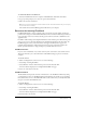
Installing and starting FreeHand This section describes how to install FreeHand on your hard disk and start the application. Before you begin, make sure your computer meets the requirements listed under “System requirements” on page 7. Read the Read Me document on the FreeHand CD for late-breaking information. To install and start FreeHand in Windows: 1 Disable any virus-protection software. 2 Insert the FreeHand CD into the computer’s CD-ROM drive. 3 Follow the onscreen instructions.
To uninstall FreeHand on the Macintosh: 1 Insert the FreeHand CD into the computer’s CD-ROM drive and launch the installer. 2 A pop-up menu prompts you to select an option. Select Uninstall. 3 Follow the onscreen instructions. Note: If you used custom installation to install FreeHand in a folder other than the default folder, you must specify the same folder when uninstalling. The installer removes all FreeHand application files from your computer.
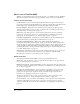
What’s new in FreeHand MX Whether you design illustrations for print media, the web, or a combination of both, FreeHand MX offers new features that enhance the approachability, creativity, and power of FreeHand. Standards and interactivity FreeHand MX has a new user interface that simplifies workflow and organizes the workspace better. The new interface makes FreeHand easier to learn if you already know other Macromedia Studio MX products, including Dreamweaver MX, Flash MX, and Fireworks MX.
Blend tool Blends are now easier to apply. The Blend tool lets you drag a line between two blend shapes to create the blend. See “Using the Blend tool” on page 213. This new feature lets you create beautiful calligraphic strokes as part of your vector objects. For more information, see “Using calligraphic stroke attributes” on page 173. Calligraphic stroke Eraser tool The new Eraser tool lets you erase parts of vector objects. To learn more, see “Erasing paths” on page 95.
Ease of use Finally, many new FreeHand MX features are dedicated to making your workflow easier than ever. The Tools panel has been reorganized to make finding and using your tools easier. To find out more, see “Using the Tools panel” on page 24. Tools panel changes Gradient fill handles increase your control in manipulating gradient fills. See “Using gradient fill attributes” on page 179.
CHAPTER 1 FreeHand Basics To get the most out of working in Macromedia FreeHand MX, it’s helpful to familiarize yourself with the FreeHand workspace, which includes the Document window, command menus at the top of your screen, tools and panels for editing and adding objects, and the pasteboard in which you create your artwork. You can add more commands to the menus by installing software applications called plug-ins, and you can add and rearrange tools in toolbars by customizing your work environment.
The Macromedia Studio MX interface FreeHand is part of the Macromedia MX product family, so it utilizes the Macromedia MX workspace, an interface that is shared by the other Macromedia MX products. Consistency among products allows users of one product to easily learn and use the others. The first time you open FreeHand, the workspace consists of the Document window and a set of docked panels.
The Document window In addition to panels, when you launch FreeHand you’ll also see the Document window and the pasteboard—the area that contains the pages of your document. The Document window contains all your documents’ objects. Objects must be placed on a page in order to be printed with the Print command; if they are placed on the pasteboard outside of page boundaries, you can print them using the Output Area feature. For more information, see “Defining an output area” on page 382.
• The Halftones, Layers, Answers, and Navigation panels are not grouped with other panels by default, but you can group them if you want. With the exception of the Properties and Assets panel groups, when you group panels together, all panel group names appear in the panel group title bar. You can, however, name panel groups anything you like; see “Grouping panels” on page 19.
To show or hide panels docked to the application window (Windows only): Click the small arrow that separates the docked panel area from the rest of the application window. Click to show or hide docked panel area To return panels to their default positions: 1 Exit FreeHand. 2 Locate the Macromedia/FreeHand/11/English/Settings folder within your user-specific Application Data (Windows) or Application Support (Macintosh) folder.
Docking panels You can dock individual panels and panel groups to one another. In Windows, you can also dock panels to the integrated application window. Panels and panel groups in Windows can be docked on the right side, left side, or both sides of the screen. To dock a panel or panel group: Drag the panel or panel group by its gripper to the desired location.
To undock a panel or panel group: Drag the panel or panel group by its gripper to the desired location. Using a panel’s Options menu Each panel has an Options menu listing a range of choices specific to the active panel. To open a panel’s Options menu: Click the Options menu control in the upper right corner of the panel group. Options menu control Grouping panels You can group panels with other panels, add them to existing panel groups, or remove them from panel groups.
To remove a panel from a group: 1 Activate the panel you want to remove from the group. 2 Select Group [Panel Name] With from the panel’s Options menu, and select New Panel Group. The panel becomes its own panel group. To rename a panel group: 1 With any panel active in the panel group, select Rename Panel Group from the panel’s Options menu. 2 Type a new name. 3 Click anywhere outside the panel group, or press Enter (Windows) or Return (Macintosh).
The Document panel displays thumbnail icons for each page in your document. Using the Pointer tool, you can move the thumbnails in the panel to move the corresponding pages on the pasteboard. You can choose from three magnified views. The Document panel also has options for adding, duplicating, and removing pages, plus options to set page size, orientation, bleed, and printer resolution. For more information, see “Using the Document panel” on page 43.
Using toolbars FreeHand has several toolbars that can either float or be docked along the top, left, and bottom of the Document window. You can customize toolbars; for more information, see “Customizing toolbars” on page 38. You can display information about each tool as the pointer passes over it (see “Using tooltips” on page 27). FreeHand has the following toolbars: • The Tools panel is actually a toolbar. Like other toolbars, it can be docked to the top or bottom of the application window.
The Main toolbar The Main toolbar contains the basic commands you use when beginning your FreeHand project. You use the Main toolbar to open document files and to manage the appearance of your document. The Main toolbar also provides quick access to many common panels. The following buttons are available on the Main toolbar by default, but you can add other buttons if you want. For more information, see “Customizing toolbars” on page 38.
Using the Tools panel The Tools panel contains tools that allow you to select, draw, and edit objects; apply color to objects; and create text. It is divided into four sections: Tools, View, Colors, and Snap. You can customize the panel by adding and removing buttons. Some tools in the Tools panel have a down arrow in the lower right corner. The down arrow indicates the presence of a tool pop-up menu.
To remove a tool from the Tools panel, do one of the following: • Select Window > Toolbars > Customize, and drag the desired button from the Tools panel. • Alt-drag (Windows) or Command-drag (Macintosh) a tool from the Tools panel. Once you remove a tool from the Tools panel, you cannot move the tool back onto the panel without using the Customize dialog box. For more information on customizing toolbars, see “Customizing toolbars” on page 38.
To find an explanation of a particular preference option or set of options, refer to the index. To display preference options: 1 Press Control+U (Windows) or Command+U (Macintosh). 2 In Windows, click a tab; on the Macintosh, click an item in the Category list.
To restore all preferences to their default settings: 1 Press Control+U (Windows) or Command+U (Macintosh). The Preferences dialog box appears. 2 Click Defaults at the bottom of the Preferences dialog box, and click OK. Using tooltips Tooltips give you information about a tool name or toolbar button. In FreeHand, tooltips appear by default; you can turn them off if you want. To display a tooltip: Pause the pointer over a button on a toolbar.
Setting the document view You can set your document view to help you work more efficiently. You can use multiple views to see several pages or documents at once, and you can create custom views. Commands in the View menu let you choose different ways to view and preview your work. You can set preferences to determine the view and page placement when opening a document.
To choose a drawing mode: Select an option from the Drawing Mode pop-up menu in the Status toolbar (Windows) or at the bottom of the Document window (Macintosh): Preview displays the document as it will print. (You can’t preview custom, PostScript, or textured strokes and fills.) Fast Preview displays blends with reduced steps and greeked (dimmed) text. Keyline displays only a black hairline stroke, no fill for objects, and X-boxes for EPS images and bitmap images.
To set how scrolling affects redrawing: 1 Display redraw preferences by doing one of the following: • In Windows, press Control+U, then click the Redraw tab. • On the Macintosh, press Command+U, then click the Redraw category. 2 Select Redraw While Scrolling to redraw the document when you click a scroll arrow or scroll bar. When this option is deselected, the document is redrawn when scrolling stops. 3 Click OK.
Magnifying and reducing the view You can zoom in or out to magnify or reduce your view using tools, menu commands, or keyboard shortcuts. Using the Zoom tool, you can create custom views based on the applied magnification. Using the View menu or the document’s Magnification pop-up menu, you can select magnifications ranging from 6% to 6400%, depending on the menu you use. In Windows, you can use the right mouse button to magnify a selected area.
To fit the view to a selection or page: Select an option from the View menu, or from the Magnification pop-up menu in the Status bar (Windows) or at the bottom of the Document window (Macintosh): Fit to Page fits the active page inside the Document window. Fit Selection Fit All fits all selected objects inside the Document window. fits all pages inside the Document window.
To edit a custom view: 1 Adjust view elements to redefine the view using the Magnification pop-up menu, Drawing Mode pop-up menu, and scroll bars. 2 Select View > Custom > Edit. 3 In the Edit Views dialog box, select a custom view name and click Redefine. Tip: To change the name of a custom view, double-click the custom view name and type a new name. 4 Click OK. To delete a custom view: 1 Select View > Custom > Edit. 2 Select the view to be deleted. 3 Click Delete; then click OK.
• Select multiple objects by pressing Shift as you select the objects or by dragging a bounding box around the objects. Right-click the selection to display common commands. • Right-click a page, color box, style, or foreground or background layer. This approach works in the Document panel, Swatches panel, Layers panel, Styles panel, and Tints panel, as well as for any color swatch, color box, or blank area of the document.
Printing a shortcut quick-reference card You can print a shortcut quick-reference card and save a custom card. To print a shortcut quick-reference card: 1 Select Edit > Keyboard Shortcuts. 2 In the Keyboard Shortcuts dialog box, click Print. 3 In the dialog box that appears, click Print again. A system Print dialog box appears. Set any desired options and click the appropriate button to send the card to your printer. To save a custom keyboard shortcut card: 1 Select Edit > Keyboard Shortcuts.
To view and choose from available shortcut groups: 1 Select Edit > Keyboard Shortcuts. The Customize dialog box (Windows) or the Customize Keyboard Shortcuts dialog box (Macintosh) appears. Shortcuts tab in Customize dialog box (Windows) Customize Keyboard Shortcuts dialog box (Macintosh) 2 36 Select a shortcut group from the Keyboard Shortcuts Setting pop-up menu.
To copy a customized shortcut group from one computer to another: 1 Select the Shortcuts file, located in the Keyboard folder within the Macromedia/FreeHand/11/ English/Settings folder in your user-specific Application Data (Windows) or Application Support (Macintosh) folder. Note: The location of your user-specific Application Data or Application Support folder varies depending on your operating system. Refer to your operating system’s documentation for information on locating this folder.
To remove a shortcut: 1 Select Edit > Keyboard Shortcuts. 2 Expand the Commands list to locate and select the desired command. 3 Select the shortcut you want to delete under Current Shortcut Keys. 4 Click Remove. 5 Click Close or select a new shortcut group to confirm the removal. Customizing toolbars To customize the form, location, and contents of a toolbar, you can use the Customize dialog box (Windows) or the Customize Toolbars dialog box (Macintosh). You can also drag toolbar buttons.
To customize toolbars using the Customize command: 1 Select Window > Toolbars > Customize. (Alternatively, in Windows you can select Edit > Keyboard Shortcuts and click the Toolbars tab.
2 Do one of the following to select the command you want to add: • Scroll through the Commands list to find the command whose button you want to place on a toolbar. If necessary, click the plus (+) sign (Windows) or the triangle (Macintosh) to expand categories. • If the command is not in a FreeHand menu, expand the Tools/Commands category. • Click a menu or menu command to highlight the associated buttons. • Click a button to highlight the associated menu command.
To dock a floating toolbar onto the top, bottom, or side toolbar area: Drag the gray area of the floating toolbar onto the top, bottom, or side toolbar area. A highlight indicates where the toolbar will be dropped if you release the toolbar at that location. The floating toolbar becomes a regular toolbar when dropped in the area surrounding the pasteboard.
Chapter 1
CHAPTER 2 Setting Up Your Document When you begin your Macromedia FreeHand MX project, you can choose among various document settings to best meet your design and final output requirements. You use the Document panel to set page options such as page size and orientation, bleed value, and final output resolution. You can also use the Document panel to define custom page sizes. You can create templates to use as defaults for creating new documents.
Working with pages You can set page options—including page size, page orientation, and bleed value—using the Document panel or the Add Pages dialog box. You can also quickly add pages to a document using the Add Page button. To set page options: 1 Select Window > Document to display the Document panel if it isn’t already open. Page size pop-up menu Page orientation Page thumbnail views 2 Select a page size from the Page Size pop-up menu.
8 To scroll the pasteboard view, hold down the Spacebar while dragging the pasteboard. To add pages to a document using the Document panel: 1 Click the Document panel Options menu control, and select Add Pages. 2 Set options in the Add Pages dialog box. 3 Click OK. To add pages to a document from the Document window, do one of the following: • Click the Add Page button at the bottom of the Document window.
• Click a page selector button in the Status toolbar (Windows) or at the bottom of the Document window (Macintosh). • Click the page in the Document window with any tool. For this to work with all tools, the Using Tools Sets the Active Page option must be selected; see the following procedure. To set how pages become active: 1 Display document preferences by doing one of the following: • In Windows, press Control+U, then click the Document tab.
To move a page and its contents, do one of the following: • Using the Page tool, select the page and drag it to the desired location on the pasteboard. • In the Document panel, select the page and drag it to the desired location. To move a page without moving its contents: 1 Using the Page tool, select the page. 2 Start dragging the page, then hold down Control (Windows) or Command (Macintosh) and continue dragging the page on the pasteboard.
Defining custom page sizes You can add custom page sizes to a document using the Edit Page Sizes dialog box. Custom page sizes are based on the document’s current unit of measure. Custom pages cannot be changed; to edit a custom page definition, you must delete and re-create it. Custom pages are retained within the FreeHand document. To make a custom page definition available to newly created FreeHand documents, you add the custom page definition to a FreeHand template.
Setting units of measure FreeHand offers precision and flexibility for entering numeric values and displaying the rulers and grid: • You can choose from points, picas, inches, decimal inches, millimeters, kyus, centimeters, or pixels to display in the rulers, panels, and dialog boxes. • You can override the default unit of measure in numeric text boxes. If you override the default unit of measure, FreeHand automatically converts the value to the default unit of measure.
Working with master pages Master pages allow you to easily apply consistent page layouts in a document. You can define page attributes on a master page, as well as place text and graphics on it, and then apply these attributes to some or all of the pages in your document. You can create more than one master page in a document. Note: You can also use templates to create documents with predefined page layouts. For more information, see “Using templates” on page 60.
To create a new master page: 1 Do one of the following: • Select Window > Document to display the Document panel if it’s not already displayed. Then click the Document panel Options menu control and select New Master Page. • Select Window > Library to display the Library panel if it’s not already displayed. Then click the Library panel Options menu control and select New Master Page.
To release a child page: 1 Select a page or pages using the Page tool. Note: The current page must be a child page. 2 Click the Document panel Options menu control and select Release Child Page. The selected page or pages are no longer based on a master page. Any objects from the master page are pasted onto the selected page or pages. One group of objects is created for each layer that contained objects.
To show or hide page rulers: Select View > Page Rulers > Show. This command toggles between showing and hiding the rulers. A check mark indicates that the rulers are visible. To change the page ruler’s zero point: Drag the zero-point marker from the upper left corner of the Document window to a new location on the pasteboard. Zero-point marker Note: Zero points can be defined for each individual page in a document. To reset the page rulers: Double-click the zero-point marker.
To delete custom units of measure: 1 Select View > Page Rulers > Edit to open the Edit Units dialog box. 2 Select the units of measure you want to delete from the Units pop-up menu. 3 Click the Minus (–) button. 4 In the alert dialog box, click OK. Then click Close. Using the grid and guides For alignment aids, you can display nonprinting lines as guides or a grid. You can change the color of these lines.
Using guides Guides are nonprinting lines that help you align and position objects. Guides are blue by default, but you can change their color if desired (see “Using the grid and guides” on page 54). You can set guides where you want them using the page rulers or the Edit Guides command. You can add, modify, and delete guides as needed. You can also lock guides in place. Guides can only exist on pages; you cannot drag them to the pasteboard.
To add guides precisely: 1 Do one of the following: • Select View > Guides > Edit. • Double-click an existing guide. 2 Click Add. 3 Select Horizontal or Vertical. 4 Choose an Add By option to add guides: • Select Count and enter a value to add a precise number of guides. • Select Increment and enter a value to add guides at set intervals. 5 Enter the first and last position of the guides. 6 Set the page range. 7 Click Add.
To edit, release, or delete guides: 1 Do one of the following: • Select View > Guides > Edit. • Double-click an existing guide. 2 Select the guide you want to modify. To modify more than one guide at a time, Control-click (Windows) or Command-click (Macintosh). Shift-click to select contiguous guides. 3 Do one of the following: • To edit a guide’s position, click Edit. In the Guide Position dialog box, enter a new location for the guide and click OK. • To release the guide or guides, click Release.
Creating and opening documents When you create a new document, it is based on the default document template. To learn more about templates, see “Using templates” on page 60. You can open a multipage document, make changes to it, and then save the document. For easy access, the four most recently saved documents appear in the File > Open Recent menu. When you quit FreeHand, you have a chance to review any unsaved documents.
To set preferences that affect how FreeHand handles documents: 1 Display document preferences by doing one of the following: • In Windows, press Control+U, then click the Document tab. • On the Macintosh, press Command+U, then click the Document category. 2 Do any of the following: • To open a document at the same magnification as when it was last saved, select Restore View When Opening Document.
Using templates To work more efficiently and avoid design inconsistencies, you can create templates for documents that share common design elements and production settings. You can then use these templates as defaults for creating new documents. You can also use master pages to apply page layouts to individual pages. For more information, see “Working with master pages” on page 50. A template’s settings and attributes are defaults for creating other documents.
To convert any FreeHand file into a template without opening it (Macintosh): 1 Select the FreeHand file in the Finder. 2 Select File > Get Info or File > Show Info and then select Stationery Pad. To convert a template into a regular FreeHand document, deselect Stationery Pad. To change the default template: 1 Display document preferences by doing one of the following: • In Windows, press Control+U, then click the Document tab. • On the Macintosh, press Command+U, then click the Document category.
5 Name the file and save it in the Macromedia/FreeHand/11/English/Settings folder within your user-specific Application Data (Windows) or Application Support (Macintosh) folder. In Windows, the extension .ft11 is added to the filename. The location of your user-specific Application Data or Application Support folder can vary depending upon your operating system. For information on how to locate this folder, see your operating system’s documentation.
6 Double-click the filename. The import pointer appears. Import pointer 7 Position the import pointer where you want the graphic or text block’s upper left corner to appear. 8 Place the graphic by doing one of the following: • Click to place the graphic at its default size. • To resize an image while importing, drag the import pointer to create a marquee. Release the mouse button when the marquee is the correct size.
To update a link to a graphic after you have opened the document: 1 Do one of the following: • Select Edit > Links to display the Links dialog box. • In the Object panel, click the Links button when the graphic is selected in the document. The Links dialog box appears, listing all imported graphic files. The file information for files with broken links appears in italics. The Kind column lists the type of image (such as TIFF, SWF, EPS, or grayscale). The Size column displays the size of the file.
Updating and fixing broken links upon opening a document If you try to open a document with a broken link to a graphic, you’ll be prompted to locate the link. To locate a missing link: 1 Select File > Open. 2 Navigate to locate the file to open. Click Open. 3 In the Locate File dialog box, navigate to locate the missing file, and select it.
Replacing missing fonts If you open or import a file containing fonts that are not installed on your system, the Missing Fonts dialog box prompts you to replace the missing fonts. Any missing fonts not replaced will display and print in the default replacement font, Arial (Windows) or Courier (Macintosh); however, the font assignment in the document remains the same. To replace missing fonts: 1 Do one of the following: • Select File > New to open a new file. Then select File > Import to import a file.
Sending mail (Windows) If your Windows system includes an MAPI32-compliant electronic mail system, you can create a new outgoing mail message with the active FreeHand document or all open documents attached. To send an e-mail message with an attached FreeHand document: 1 Select File > Send. 2 Do one of the following: • To attach the active document to your e-mail message, select the filename. • To attach all currently open documents to your e-mail message, select All Open Documents.
Working with wizards (Windows) In Windows, you can quickly begin a project and simplify your workflow using FreeHand wizards. Wizards are interactive screens that guide you through and simplify a variety of tasks. To use a wizard: 1 Select Help > Wizards. 2 Select a topic: lets you create a new document, open the previous document, select and open a document from a list, open a template, or launch FreeHand Help. This screen appears when you launch FreeHand.
CHAPTER 3 Drawing Macromedia FreeHand MX gives you a wide range of options for drawing. You can drag to create simple objects, such as rectangles, ellipses, and lines. You can also drag to create more complex shapes, including spirals, stars, and polygons. Most drawing tools let you set options. For example, you can change the number of sides on a polygon or the direction in which a spiral winds.
In contrast, bitmap images consist of a matrix of pixels whose display depends on the resolution of your monitor and printer. Bitmap images appear granulated when enlarged. Vector image (top) and bitmap image (bottom) FreeHand is a vector drawing program, but you can work with bitmap images in several ways. You can rasterize FreeHand objects, which means to convert them to bitmap images within your document. For more information, see “Converting vector graphics to bitmap images” on page 326.
Path and point characteristics Paths and points have the following basic characteristics: • A path can be open with unconnected end points, or closed with the same beginning and ending point. Examples of open (top) and closed (bottom) paths • Each path can have up to 32,000 points, which lets you import complex files from other sources. However, using more points increases file size and slows redrawing and printing.
• Paths have either clockwise or counterclockwise direction. The Rectangle, Polygon, and Ellipse tools draw in a clockwise direction. With the Line tool, the direction in which you draw sets the path direction. With the Pen and Bezigon tools, the order in which you place points sets the path direction. Ending point Beginning point Beginning and ending point The path direction affects path operations (see “Changing a path’s direction” on page 95) and blending.
• Different types of points anchor path segments and let you edit lines and curves in different ways by adjusting their handles. Corner point Connector point Curve point FreeHand places a corner point, which is displayed as a square, when you draw a straight path segment. A corner point’s handles can be adjusted independently. When you first select a corner point, its handles are retracted. FreeHand places a curve point, which is displayed as a circle, when you draw a curved path segment.
To set the display preferences for a fill in an open path: 1 Display object preferences by doing one of the following: • In Windows, press Control+U, then click the Object tab. • On the Macintosh, press Command+U, then click the Object category. 2 Select Show Fill for New Open Paths if you want an open path’s fill to be displayed. This option applies only to paths created after you have set this preference. 3 Click OK.
To draw a rectangle, ellipse, or line from its center: 1 In the Tools panel, select the Ellipse tool, or select the Rectangle or Line tool from its pop-up menu. 2 Hold down Alt (Windows) or Option (Macintosh) as you drag the respective tool. Drawing rectangles with curved corners You can precisely edit the curvature of rectangle corners by using the Object panel. The corners of a rectangle can be uniform, or you can edit corners individually by unlocking them in the Object panel.
To adjust the corners of a selected rectangle independently: 1 In the Tools panel, click the Subselect tool. 2 Select the rectangle. 3 In the Object panel, deselect Uniform. 4 Drag a radius handle. Constraining a basic shape as you draw You can constrain how a tool draws a basic shape. When constrained, the Rectangle tool draws a square, the Ellipse tool draws a circle, and the Line tool draws at increments of 45°. You can change the constrain angle.
To set the constrain angle: 1 Select File > Document Settings > Constrain. 2 Enter a value in the Angle text box, or use the pop-up angle dial to set the angle. 3 Click OK. Repositioning a basic shape as you draw You can move a rectangle, line, ellipse, polygon, or star as you draw. To reposition a basic shape while drawing, do one of the following: • Hold down the Spacebar. • (Windows only) Hold down the right mouse button.
To draw a polygon or star: 1 In the Tools panel, select the Polygon tool from its pop-up menu. 2 Drag to draw a polygon or star. 3 To modify the polygon or star as you draw, use any of the following keys: • Press Shift to constrain the angles of the polygon. • Press Alt (Windows) or Option (Macintosh) to draw from the center regardless of the selected drawing option. To edit a polygon or star: 1 In the Tools panel, click the Subselect tool. 2 Select the polygon or star.
Drawing spirals and arcs With the Spiral and Arc tools, you can easily draw spirals and arcs. Options let you customize the way each tool works. To set Spiral tool options: 1 In the Tools panel, if the Spiral tool is not showing, select it from its pop-up menu. 2 Double-click the Spiral tool. 3 In the Spiral dialog box, select a Spiral Type option: • Click the left button to create a spiral with a concentric, evenly spaced radius.
To set Arc tool options: 1 In the Tools panel, if the Arc tool is not showing, select it from its pop-up menu. 2 Double-click the Arc tool. 3 In the Arc dialog box, select from the following options: Create Open Arc lets you draw only the arc curve. Deselect this option to draw the arc as a quarter pie shape. Create Flipped Arc lets you flip the orientation of the arc. Create Concave Arc lets you draw the arc with an outer corner. Concave (left), Open (center), and Flipped (right) 4 Click OK.
Drawing freeform paths With the Pencil, Variable Stroke Pen, and Calligraphic Pen tools, you can draw freeform paths that follow the direction of your hand movements. Drawing with the Pencil tool The Pencil tool draws a simple line as you drag. To set Pencil tool options: 1 In the Tools panel, if the Pencil tool is not showing, select it from its pop-up menu. 2 Double-click the Pencil tool.
• Select Auto Remove Overlap to remove unnecessary path segments and create a composite path. Original (left) and Auto Remove Overlap applied (right) Note: Using the Auto Remove Overlap option may slow the redrawing of an image. You can also remove any overlap by selecting the path and choosing Modify > Alter Path > Remove Overlap or clicking the Remove Overlap button on the Xtra Operations toolbar.
• Select Auto Remove Overlap to remove unnecessary path segments and create a composite path. Original (left) and Auto Remove Overlap applied (right) Note: Using the Auto Remove Overlap option may slow the redrawing of an image. You can also remove any overlap by selecting the path and choosing Modify > Alter Path > Remove Overlap or clicking the Remove Overlap button on the Xtra Operations toolbar.
To draw a path with the Calligraphic Pen tool: 1 In the Tools panel, select the Calligraphic Pen tool from its pop-up menu. 2 Drag to draw a path. 3 To alter the path as you draw, do any of the following: • Hold down Alt (Windows) or Option (Macintosh) to draw a straight line. • To decrease the path width, press the Left Arrow key (Windows) or Left Bracket key (Macintosh). • To increase path width, press the Right Arrow key (Windows) or the Right Bracket key (Macintosh).
To draw with the Pen tool: 1 In the Tools panel, select the Pen tool from its pop-up menu. 2 Do any of the following: • Click to place a corner point. • Drag to place a curve point and extend its handles. Press Control (Windows) or Command (Macintosh) as you drag to move the curve point to a new location. • Hold down Alt and right-click (Windows) or Control-click (Macintosh) to place a connector point. Dragging as you place a connector point extends the point’s handle.
To continue an unselected path: 1 In the Tools panel, select the Pen tool or Bezigon tool from their pop-up menu. You can continue a Pen path with the Bezigon tool and vice versa. 2 Move the pointer over an end point of the path you want to continue. 3 Alt-drag (Windows) or Option-drag (Macintosh) to extend the path. 4 Click or drag to draw additional segments.
To automatically add points to a selected path: Select Window > Toolbars > Xtra Operations. Click the Add Points button on the Xtra Operations toolbar, or select Xtras > Distort > Add Points. A point is added halfway between every pair of points on a path. Reshaping a path Using the Pointer and Subselect tools, you can reshape a path by moving points and path segments. You can also adjust the points on a path by dragging with the Pointer tool or by using the Object panel.
4 Drag a handle to adjust the curve. Moving a handle closer to its point decreases the amount of curvature. Moving it away from the point increases the curve. Dragging a corner point’s handle to curve a straight path segment Dragging a curve point’s handle to reverse a path segment’s curve Dragging a connector point’s handle to increase a path segment’s curvature The farther you drag a handle from a corner, curve, or connector point, the more pronounced the curve becomes.
To adjust points using the Object panel: 1 Select Window > Object to display the Object panel. Path information in the Object panel 2 Select the path and then the points you want to adjust. The Object panel displays several options for the selected points. If you select more than one point, the Point location text boxes are hidden.
3 Do one of the following: • Click a Point Type button to change the type of the selected point. • Click a Handles button to retract the selected point’s handles. • Select Automatic to extend the point handles and adjacent path segments to best conform to the existing path. This option may move curve point handles from their original position, but does not add handles to corner or connector points. • Change a point’s location by editing the values in the Point Location X and Y text boxes.
To set Freeform tool Push/Pull options: 1 In the Tools panel, if the Freeform tool is not showing, select it from its pop-up menu. 2 Double-click the Freeform tool. 3 In the Freeform Tool dialog box, select Push/Pull. 4 Select the Push Settings options: • Set the pointer size in pixels by entering a value from 1 to 1000 in the Size box or by adjusting the slider. • Set the tool precision by entering a value from 1 to 10 in the Precision box or by adjusting the slider.
To push or pull a selected path: 1 In the Tools panel, if the Freeform tool is not showing, select it from its pop-up menu. 2 You can adjust the path two ways: • Click on the path and drag to pull the path. A small s beside the pointer indicates that you are in Pull mode. Pulling a path segment between points (top) and pulling a path of a specified length (bottom) • Click beside the path and drag to push the path. A circular pointer indicates that you are in Push mode.
To set Freeform tool Reshape options: 1 In the Tools panel, if the Freeform tool is not showing, select it from its pop-up menu. 2 Double-click the Freeform tool. 3 In the Freeform Tool dialog box, select Reshape. 4 Select the Settings options: • Set the pointer size in pixels by entering a value from 1 to 1000 in the Size box or by adjusting the slider.
Splitting paths You can manually split paths and create open or closed paths by using the Knife tool or the Split command. To set the Knife tool options: 1 In the Tools panel, double-click the Knife tool. 2 Select options in the Knife Tool dialog box: • Select Freehand to make a freehand cut or Straight to make a straight cut. If you are using the Freehand operation, you can hold down Alt (Windows) or Option (Macintosh) as you drag to cut a straight line. Hold down Shift to constrain it.
Erasing paths You can erase parts of selected paths by using the Eraser tool. To set the Eraser tool options: 1 In the Tools panel, double-click the Eraser tool. 2 Enter a value from 0 to 72 points in the Min text box, or set the minimum width with the slider. 3 Enter a value from 0 to 72 points in the Max text box, or set the maximum width with the slider. To erase a selected path with the Eraser tool: 1 In the Tools panel, click the Eraser tool. 2 Drag the Eraser tool across the path.
Overlapping fills Closed paths have one of two directions: clockwise or counterclockwise. When a clockwise path meets a counterclockwise path, these paths yield a transparent, overlapping section in a composite path. When two closed paths of the same direction overlap, these paths yield a filled, overlapping section. If your composite path’s overlapping fill does not behave as expected, try correcting its direction, or subselect one path and reverse its direction.
7 To set the data precision, enter a Decimal Precision value for the number of decimal places to which the data will be rounded. Select Thousands Separator to punctuate values of one thousand or greater. 8 Continue entering data as needed, repeating steps 3 through 7. Note: The Chart tool plots empty cells as values of 0. 9 When you have finished entering data, click Apply to create the chart, or click OK to create the chart and close the dialog box.
Setting the chart type and options You can select different chart types and options, and preview how the data will be presented, either as you create the chart or afterwards. Options vary according to the chart type. To choose a chart type for a selected chart: 1 In the Tools panel, if the Chart tool is not showing, select it from its pop-up menu. 2 Double-click the Chart tool. 3 In the Chart dialog box, click the Chart Type button to display the chart type options.
To specify chart options: 1 In the Chart dialog box, click the Chart Type button to display the chart type options. 2 Select a chart type using the buttons and then select options for that type: • For Grouped Column and Stacked Column graphs, specify a column width to adjust the space of each column. Values greater than 100 overlap columns. • For a Grouped Column graph, specify a cluster width to adjust the space for each group of columns. Values greater than 100 overlap columns.
Displaying axis values You can display values along the axes of a chart to control how the numerical data is presented. If an axis has no numerical values, the options in the Chart Type dialog box are dimmed. The axis value options are not available for a Pie chart. To display axis values: 1 Select the chart. 2 In the Tools panel, if the Chart tool is not showing, select it from its pop-up menu. 3 Double-click the Chart tool.
Adding pictographs to charts Pictographs represent data visually, according to the type of data shown. For example, instead of a simple bar to represent a dollar amount, you can add a pictograph of a dollar sign or a stack of coins. To create a pictograph: 1 Select and copy the FreeHand graphic you’d like to use. 2 Use the Subselect tool to select a column in the series to which you’ll apply the pictograph. 3 Select Xtras > Chart > Pictograph.
Dynamically linking objects You can use the Connector tool to draw connector lines that dynamically link objects together. Connector lines automatically adjust when you move connected objects in the document window. Use connector lines for tasks such as drawing call-out lines for labels, building organizational charts, or creating basic flowcharts. You can use the Object panel to edit the start symbol, end symbol, and other stroke attributes of connector lines.
2 Select the connector line to display its handles. 3 Drag a handle to reshape the connector line. Drawing with the Graphic Hose tool For quick illustration, you can use the Graphic Hose tool to “spray” frequently used objects on your document page.
The Graphic Hose dialog box lets you store up to 10 images (including bitmaps, groups, blends, text, envelopes, and symbols) in each hose. When you paint with the hose, the images are applied in an order based on the options you choose. FreeHand comes with a collection of predefined hoses. You can edit these hoses or create your own. To select a graphic hose: 1 In the Tools panel, if the Graphic Hose tool is not showing, select it from its pop-up menu. 2 Double-click the Graphic Hose tool.
Creating a graphic hose In a graphic hose, you can include up to 10 objects. These objects can be from your current FreeHand document or from other documents. You can also use symbols as elements in a hose. By using symbols, you can modify the symbol element to update all objects created by the graphic hose automatically. For more information, see “Using the Library panel” on page 297. To create a graphic hose: 1 In the Tools panel, if the Graphic Hose tool is not showing, select it from its pop-up menu.
Setting graphic hose options You can set options for painting with the graphic hose, including the order of objects, spacing, scale, and rotation of objects. To set graphic hose options: 1 In the Tools panel, if the Graphic Hose tool is not showing, select it from its pop-up menu. 2 Double-click the Graphic Hose tool. 3 In the Graphic Hose dialog box, click Options. 4 Select an order in which objects in the set are applied: Loop applies objects in numeric order.
CHAPTER 4 Working with Objects Macromedia FreeHand MX lets you manipulate objects in a number of ways. You can group objects to treat them as a single unit and nest groups within a group. You can move objects using the mouse or keyboard or by specifying a precise location. You can align objects to each other or align them to the page. You can also transform objects by rotating, scaling, skewing, and reflecting.
Above the Properties list are buttons that allow you to add and delete properties such as fills, strokes, and effects. You can add more than one fill, stroke, and effect to an object. By dragging properties in the list, you can rearrange the order in which properties are applied to a selected object. Properties for an object with multiple strokes and fills Most changes you make to an object’s attributes are immediately applied in the Document window.
Selecting objects You can select objects with the Pointer, Subselect, and Lasso tools, or by using keyboard shortcuts or menu commands. The Pointer, Subselect, and Lasso tools let you select objects or points by clicking. The Pointer and Subselect tools also let you select objects or points by dragging a rectangular selection marquee. The Lasso tool lets you select objects and points by dragging a free-form selection marquee.
To select an object using the Lasso tool: Drag the Lasso tool to define a selection marquee around the object or points you want to select. To add an object to a selection: Hold down Shift as you select an object or point. To select all objects on the active page, do one of the following: • Select Edit > Select > All. • Press Control+A (Windows) or Command+A (Macintosh). To select all objects in a document, do one of the following: • Select Edit > Select > All in Document.
Hiding objects You can hide objects to prevent them from being modified. You can select View > Show All to redisplay hidden objects. Hidden objects will automatically redisplay when you close and re-open a file. Hidden objects appear in printed documents unless they reside on a nonprinting layer or a background layer. For more information about nonprinting and background layers, see “Using layers” on page 289. To hide selected objects: 1 Select the objects you want to hide.
Moving objects You can move selected objects directly by dragging them in the Document window or by using the arrow keys. When moving an object with the arrow keys, you can specify the distance it moves each time you press an arrow key. You can also move selected objects numerically by entering values in the Object panel or the Transform panel. When you move an object numerically using the Object panel, the values you enter define the coordinates of the object relative to the page’s zero-point marker.
To move selected objects using the Object panel: 1 Select Window > Object to display the Object panel if it’s not already displayed. 2 Select the object name in the Properties list of the Object panel if it’s not already selected. 3 In the bottom half of the panel, enter a positive value in the X text box to move the object to the right or a negative value to move it to the left. 4 Enter a positive value in the Y text box to move the selection up or a negative value to move it down.
To snap a selected object or point to a path: 1 Do one of the following: • Click the Snap to Object button in the Tools panel, if it’s not already selected. • Select View > Snap to Object, if it’s not already enabled. (A check mark beside it means it’s enabled.) Note: Snap to Object is a toggle; choosing it when it’s already enabled turns it off. 2 Using the Pointer tool, drag the selected object near or onto the target path. When you get within the snap distance, the pointer changes.
To align or distribute selected objects or points: 1 Select Window > Align to display the Align panel. Click edge to align objects to top, bottom, left, or right. Horizontal options Vertical options Click in a square to align vertically and horizontally. The three rectangles in the preview illustrate the current alignment settings; when you select a distribution option, a fourth rectangle appears. 2 Do one of the following: • In the preview window, click to set alignment options.
You can choose from the following formats for FreeHand copy operations: • • • • • • • • • • FreeHand RTF AI/EPS (Windows) EMF (Windows) Metafile (Windows) Bitmap (Windows) Device independent bitmap (Windows) Adobe Illustrator (Macintosh) ASCII (Macintosh) PICT (Macintosh) You can also choose the color space you want for the copied selection. In Windows, this choice is only available if you have selected AI/EPS.
To set copy format preferences: 1 Display export preferences by doing one of the following: • In Windows, press Control+U, then click the Export tab. • On the Macintosh, press Command+U, then click the Export category. 2 In the Clipboard Copy Formats list (Windows) or Clipboard Output Formats (Macintosh), select the formats you want FreeHand to use when copying to the Clipboard. Deselected formats are not available for copying.
To disable copying when Alt-dragging (Windows) or Option-dragging (Macintosh): 1 Display object preferences by doing one of the following: • In Windows, press Control+U, then click the Object tab. • On the Macintosh, press Command+U, then click the Object category. 2 Deselect Alt-Drag Copies Paths (Windows) or Option-Drag Copies Paths (Macintosh), and click OK. To clone or duplicate a selected object, do one of the following: • To duplicate the object, select Edit > Duplicate.
Copying objects between applications You can copy objects between a FreeHand document and a document in another application by copying and pasting with the Clipboard or, in some cases, by dragging. When you copy to or paste from the Clipboard, FreeHand normally chooses the best format from the available ones you set in preferences. Using the Copy Special command, you can force FreeHand to convert the selection on the Clipboard to a specific file format.
Objects within a group retain their original stroke and fill attributes. You can modify these attributes by subselecting objects within the group and making changes in the Object panel. You can also modify the attributes of the group as a single object, which applies the attributes to the group as a whole; this approach does not alter the original attributes of the individual objects.
To select an object within a group: 1 Do one of the following: • Click the Subselect tool and click the object to select it. • Using the Pointer tool, hold down Alt (Windows) or Option (Macintosh) and click the object to select it. 2 To add objects to the subselection, press Shift as you subselect. To select an object behind another object in a group: 1 Click the Pointer tool. 2 Do one of the following: • In Windows, hold down Control+Alt and right-click to cycle through selected objects.
Working with nested objects Nested objects are objects in groups within larger groups. You can manipulate them just as you would any other group. To nest an object or group within an existing group: 1 Select an object or group that you want to nest. 2 Hold down Shift as you select the group into which you want to nest the selection. 3 Select Modify > Group. You can apply the Group command up to 20 times in succession to nest objects within a group, or to combine groups within a larger group.
Arranging objects You can change the stacking order of objects by using the Arrange commands or by cutting and pasting. (The stacking order may not be obvious if the objects do not overlap.) You can integrate an object into a group or clipping path by pasting the object behind or in front of another object within a group or a clipping path. For more information on clipping paths, see “Working with clipping paths” on page 132.
Adding names and notes to objects You can name an object or add a note to it by using the Navigation panel. You can also use the Navigation panel to check object names and notes. Names and notes can be exported as annotations when you export a FreeHand drawing to PDF format. For more information, see “Exporting PDF files” on page 358. You can also add URL links to objects and text. For information, see “Attaching URLs to objects and text” on page 327.
To select objects by attributes: 1 Select Edit > Find and Replace > Graphics, or click the Graphics button in the Main toolbar. 2 Click the Select tab. 3 Use the Attribute pop-up menu to choose what to select: Color selects objects with the specified color. Style selects objects with a specified style name. Same as Selection Fill Type selects objects with matching strokes or fills. selects objects with a designated fill type. Stroke Type selects objects with a designated stroke type.
Finding and replacing graphics The Find & Replace panel lets you search for and automatically change attributes including color, stroke width, transformations, path shapes, and blend steps. The feature lets you modify every occurrence of a specific attribute, including all occurrences of the attribute in hidden objects. You can replace a selection or object in a page or document. The stroke width, simplify, rotate, scale, and blend steps attributes can be calculated mathematically.
Combining paths You can create new paths by joining or combining paths. Some of these operations produce composite paths, which consist of individual paths joined together that act as one path. When you combine paths using the Join command, the selected paths are simply joined as a single composite path.
To adjust the transparent sections of a composite path: 1 Select a composite path. 2 Select Window > Object to display the Object panel if it’s not already displayed. 3 Do one of the following: • Select Even/Odd Fill to make overlapping subpaths of a composite path alternate between filled and transparent. • Deselect Even/Odd Fill to make overlapping subpaths filled or transparent based on their path direction. For more information on path direction, see “Path and point characteristics” on page 71.
Using the Union command Union combines two or more closed paths into a single path, enclosing the entire area of the original paths. If the selected path does not touch the other paths, the result is a composite path. To apply the Union command to selected paths, do one of the following: • Select Modify > Combine > Union. • Select Window > Toolbars > Xtra Operations to display the Xtra Operations toolbar if it’s not already displayed, and click the Union button.
To apply the Divide command to selected paths, do one of the following: • Select Modify > Combine > Divide. • Select Window > Toolbars > Xtra Operations to display the Xtra Operations toolbar if it’s not already displayed, and click the Divide button. (For more information on working with Xtras, see “Using and managing Xtras” on page 27.) • Select Xtras > Path Operations > Divide.
Using the Punch command Punch removes parts of selected, closed paths below the topmost, closed path. The front selected path is deleted as its shape punches a hole. Where a hole is fully enclosed within a path, a punched path becomes a composite path. Stroke and fill attributes remain unchanged. To apply the Punch command to selected paths, do one of the following: • Select Modify > Combine > Punch.
To apply the Crop command to selected paths, do one of the following: • Select Modify > Combine > Crop. • Select Window > Toolbars > Xtra Operations to display the Xtra Operations toolbar if it’s not already displayed, and click the Crop button. (For more information on working with Xtras, see “Using and managing Xtras” on page 27.) • Select Xtras > Path Operations > Crop. Working with clipping paths You can fill a closed path with other objects: vector graphics, text, or bitmap images.
2 Position the objects the way you want them to appear as the contents in the clipping path. 3 Select Edit > Cut. 4 Select a closed path to use as the clipping path. 5 Select Edit > Paste Contents. 6 Select the Contents property in the Properties list of the Object panel. When a clipping path’s contents are selected, a paste contents handle appears on top of the contents in the workspace. By dragging this handle, you can reposition the contents.
To set transformation options for a selected clipping path: 1 Do one of the following: • Select Modify > Transform > Move. • Select Window > Transform, and click the Move button. 2 In the Transform panel, do one of the following: • Select Contents if you want transformations applied to the clipping path to apply to the contents. • Deselect Contents if you don’t want transformations applied to the clipping path to apply to the contents.
To expand the stroke of a selected path using menu commands or Xtras: 1 Do one of the following: • Select Modify > Alter Path > Expand Stroke. • Select Windows > Toolbars > Xtra Operations to display the Xtra Operations toolbar if it’s not already displayed, and click the Expand Stroke button. • Select Xtras > Path Operations > Expand Stroke. 2 In the Expand Stroke dialog box, enter a value in the Width text box or adjust the width using the slider. 3 Adjust the Cap, Join, and Miter Limit settings.
To create an inset path of a selected path: 1 Do one of the following: • Select Xtras > Path Operations > Inset Path. • Select Modify > Alter Path > Inset Path. • Select Windows > Toolbars > Xtra Operations to display the Xtra Operations toolbar if it’s not already displayed, and click the Inset Path button. 2 In the Inset Path dialog box, enter the number of paths to create in the Steps text box. A value of 1 replaces the selected object; a larger value creates the specified number of paths.
Using the transformation tools The transformation tool pop-up menu in the Tools panel consists of the following: • • • • The Scale tool enlarges or reduces objects. The Rotate tool applies two-dimensional rotations. The Reflect tool flips an object. The Skew tool slants an object along a specified axis. To transform a selected object using the transformation tools: 1 Click or select a transformation tool in the Tools panel.
To set an object’s center point manually: 1 Click the Pointer tool in the Tools panel. 2 Double-click the object. The object’s transform handles and center point appear. 3 Drag the center point to the new location. 4 To reset a center point, deselect and then reselect the object, or hold down Shift and click the center point. To rotate a selected object: 1 Do one of the following: • In the Tools panel, if the Rotate tool is not showing, select it from its pop-up menu; then double-click it.
4 Enter a value in the Copies text box. A value of 0 rotates only the selected object. Higher values create the specified number of copies, each of which is progressively rotated. 5 Set the object’s center manually or by entering values in the X and Y text boxes in the Transform panel. 6 Click the Rotate button. To scale a selected object: 1 Do one of the following: • In the Tools panel, if the Scale tool is not showing, select it from its pop-up menu; then double-click it.
4 For vertical scaling, enter a positive value in the Y text box to enlarge the selection or enter a negative value to reduce it. 5 Enter a value in the Copies text box. A value of 0 scales only the selected object. Higher values create the specified number of copies, each of which is progressively scaled. 6 Set the object’s center manually or by entering values in the X and Y text boxes in the Transform panel. 7 Click the Scale button.
5 Enter a value in the Copies text box. A value of 0 skews only the selected object. Higher values create the specified number of copies, each of which is progressively skewed. 6 Set the object’s center manually or by entering values in the X and Y text boxes in the Transform panel. 7 Click the Skew button. To reflect a selected object: 1 Do one of the following: • In the Tools panel, if the Reflect tool is not showing, select it from its pop-up menu; then double-click it.
4 Enter 0 or 1 in the Copies text box. Entering a higher number causes multiple copies of the object to be stacked on top of each other. 5 Set the object’s center manually or by entering values in the X and Y text boxes in the Transform panel. 6 Click the Reflect button. Transforming objects freely You can use transform handles to freely transform objects, including text blocks, and to combine a series of transformations.
To transform freely: 1 Using the Pointer tool, double-click the object you want to transform. Eight transform handles appear around the selection, and a circle appears at the selection’s center point. To disable the transform handles, double-click away from the selection. Moving the Pointer tool over and around the selection changes the pointer (cursor) to indicate which transformation function is available.
• To scale the selection, position the pointer on a transform handle, and drag. Shift-drag or drag a corner handle to resize proportionally. • To skew the selection, position the pointer on the dotted outline between the transform handles and drag. Shift-drag to constrain the skew horizontally or vertically. 3 To copy the selection as you transform it, click and hold a handle, hold down Alt (Windows) or Option (Macintosh), and drag the handle. A plus (+) sign next to the pointer indicates copying.
Power-duplicating Power-duplicating is the process of repeating a transformation (move, scale, skew, reflect, rotate) on successive duplicates of the object. You can use power-duplication with more than one transformation. For example, you can move, scale, and skew a duplicate, and those transformations will be applied to successive duplicates. Moving (left); moving and scaling (center); and moving, scaling, and rotating Note: You cannot combine scaling and skewing during power-duplication.
To set the number of undo levels: 1 Display general preferences by doing one of the following: • In Windows, press Control+U, then click the General tab. • On the Macintosh, press Command+U, then click the General category. 2 Enter a value between 1 and 100 in the Undo’s text box. Setting the level to more than 10 uses additional computer memory. 3 Click OK. For this change to take effect, you must close and reopen the document or open a new document.
CHAPTER 5 Working with Color In Macromedia FreeHand MX you can apply colors to objects using various techniques, and using colors from various color models. Whether for print, onscreen, or both, you can add, remove, name, and edit colors. FreeHand makes global color changes to a selection easy, without affecting the colors of unselected objects. You also can import and export color palettes and settings for use in other applications or FreeHand drawings.
To apply color to a selected object, do one of the following: • In the Swatches panel, drag a swatch to the Fill, Stroke, or Both color selector at the upper left of the Swatches panel. • In the Swatches panel, click the Fill, Stroke, or Both selector at the upper left of the Swatches panel, and then select a color name in the list. • In the Object panel, select the stroke or fill to which you want to apply a color, and then select a color from the Swatches panel.
Spot and process colors Spot and process colors correspond to the two main ink types used in commercial printing. A process color is printed by combining the four standard CMYK process inks: cyan, magenta, yellow, and black. By blending these inks in varying proportions, the printer can reproduce most colors. A spot (or custom) color is a special premixed ink that is used with, or instead of, CMYK process inks. A spot color requires its own plate on the press.
Using the Color Mixer panel Use the Color Mixer panel to define colors, to adjust hue, lightness, and saturation, and to select colors from the System Color dialog box. Controls in the Color Mixer panel let you choose from four color modes and add colors to the color list in the Swatches panel. Original New Add to Swatches panel Change attribute color Both the Color Mixer panel and the Tints panel use the same color box to display a color as you edit it.
To change a color mode: Click a color mode button in the Color Mixer panel. CMYK RGB HLS System Color mode buttons for Windows (left) and Macintosh (right) To define a CMYK color or an RGB color: 1 Click the CMYK or RGB mode button to change color modes. 2 To adjust color component values, move the sliders or enter values in each entry text box. Use the color box to monitor the color as you mix it.
6 To add the new color to the Swatches panel, do one of the following: • Click the Add to Swatches button. Enter a name for the color, and then specify Spot or Process. Click Add. • Drag a color swatch from the color box to the color list at the bottom of the Swatches panel. (For more details, see “Adding colors to the Swatches panel” on page 154.) Using the Tints panel Tints are lighter versions of a color. You create them by specifying a percentage of the original color.
4 To add the new tint to the Swatches panel, do one of the following: • Click the Add to Swatches button. • Drag a color swatch from any of the Tints panel color boxes to the arrow button in the Swatches panel (for more information, see “Adding colors to the Swatches panel” on page 154). The tint’s name is preceded by the percentage of the original color it represents.
The Swatches panel uses italics to display process color names and uses plain type to display spot color names. It also displays a triple-dot icon next to RGB colors, no icon for CMYK colors, and a black hexagon for Hexachrome colors. RGB colors include those created in HLS mode, the Apple Color Picker (Macintosh), and the System Color Picker dialog box (Windows).
• Drag a color from the color box of the Color Mixer or Tints panel either to the empty space at the bottom of the list of swatches or onto the arrow button at the top of the Swatches panel. Drag onto an existing color swatch to replace a color. • In Windows, right-click any color box in the Color Mixer or Tints panel and select Add to Swatches from the context menu. This bypasses the dialog box and adds the color with a default name. To duplicate a color: 1 In the Swatches panel, select a color name.
The Name All Colors Xtra adds all unnamed colors used in a document to the Swatches panel with default names. The Name All Colors Xtra also lists any colors you have created by applying the Xtras that manipulate colors, such as Color Control, Desaturate, Darken, Lighten, Randomize, or Saturate Colors. (For more information, see “Editing colors” on page 161.) The Name All Colors Xtra does not name colors in bitmap images.
Converting between RGB and CMYK When creating artwork and printing it, you can specify color as RGB or CMYK in the Swatches panel. For more information on color management, see Chapter 13, “Color Management,” on page 363. You can also convert colors in the Separations panel in the Print Setup dialog box. For information on converting RGB colors to process colors when printing a document, see Chapter 14, “Printing,” on page 375.
Adding colors from color libraries FreeHand comes with predefined spot- and process-color libraries that are part of commercially available color-matching systems. Color-matching systems provide printed and onscreen color swatches for designers and contain instructions for print professionals so that they can print the colors you specify. Consult with your commercial printer to learn which color libraries they support and recommend.
To add colors from a color-matching system library or custom color library: 1 Click the Swatches panel Options menu control and do one of the following: • Select a library from the Options pop-up menu. PANTONE Hexachrome Coated color library • If a custom color library is stored outside the Color folder in the FreeHand application folder, select Import from the Options pop-up menu to locate and open the library. 2 In the Library dialog box, select colors that you want to add to the Swatches panel.
Managing the color list in the Swatches panel You can sort colors by name, rearrange colors, hide or show color names, and delete unused colors from your artwork. FreeHand sorts colors (other than the defaults) first numerically and then alphabetically. You can change the Swatches panel to show only color swatches and hide color names. Changing the panel lets you display more colors at the same time. The active color is outlined with a solid border.
Removing colors Removing colors from the color list in the Swatches panel retains the colors in any corresponding objects as unnamed colors. When you remove multiple colors, a dialog box prompts you either to remove all colors or to remove only the unused colors. Removing spot, Hexachrome, and tint colors does the following: • Spot colors are converted to process colors. Objects containing these spot-to-process converted colors may not print separations as intended.
To brighten or dull colors: 1 Select an object. 2 Select Xtras > Colors and then select an option: Lighten Colors makes the color lighter. Darken Colors makes the color darker. Saturate Colors makes the color more intense. Desaturate Colors dulls the color. The effect increases each time you apply the Xtra until the maximum effect is reached. Controlling color values The Color Control Xtra adds or subtracts a percentage of a CMYK, RGB, or HLS color value to or from all colors in a selection.
Making global color changes You can replace all colors of the same name in your artwork by replacing the global process color or spot color swatches in the Swatches panel. See “Finding and replacing graphics” on page 126. You can also randomly change all of the colors in the color list, using the Randomize Named Colors Xtra. Experiment with this Xtra to create new color combinations. You cannot replace the default Black, White, None, or Registration colors.
Exporting colors You can export colors from the color list in the Swatches panel to use as a color library, which you can then use in other documents. When you export artwork to some file formats, you can also choose to convert the colors to RGB or CMYK. For more information, see “Saving files” on page 341. To create a custom color library by exporting colors: 1 Click the Swatches panel Options menu control and select Export.
CHAPTER 6 Using Strokes and Fills You can apply colors to strokes and fills several ways in Macromedia FreeHand MX: by using the Object panel, by dragging colors, by choosing colors from the pop-up color palettes on the Tools panel, and by using the Eyedropper tool to copy colors from other objects in the document. In addition to basic colors, you can also apply a variety of advanced stroke and fill effects to objects.
To add a stroke to a selected object, do one of the following: • Click the Add Stroke button in the Object panel. • Click the Object panel Options menu control and select Add Stroke. To add a fill to a selected object, do one of the following: • Click the Add Fill button in the Object panel. • Click the Object panel Options menu control and select Add Fill. To delete a stroke or fill from a selected object: 1 Select the stroke or fill in the Object panel.
To edit the list of preset stroke widths: 1 Display object preferences by doing one of the following: • In Windows, press Control+U, then click the Object tab. • On the Macintosh, press Command+U, then click the Object category. 2 In the Default Line Weights text box, enter the values in points. Separate values with a space. 3 Click OK. 4 Relaunch FreeHand for the changes to take effect. Using basic stroke attributes Paths that use Basic stroke attributes are simple lines.
6 To avoid beveling a Miter join, enter a Miter limit from 1 to 57. Line lengths exceeding this value are squared off instead of pointed. For example, a miter limit of 2 for a 3-point stroke means that when the length of the point is twice the stroke weight, FreeHand switches to a Bevel join. Miter (left) and Beveled (right) joins, with arrows showing the length of the Miter join 7 To apply a dashed stroke, select a style from the dash style pop-up menu. Select No Dash for a solid stroke.
To create an arrowhead from an existing one: 1 In the Object panel, hold down Alt (Windows) or Option (Macintosh) and select an arrowhead from the Arrowhead pop-up menus to display the Arrowhead Editor. The Arrowhead Editor provides a subset of FreeHand tools, including the Pen tool, for drawing or editing. 2 Edit the arrowhead. 3 Click New to add the new arrowhead to the Arrowheads pop-up menu. Note: The Arrowheads pop-up menus can display up to 255 arrowheads.
3 In the Edit Brush dialog box, type a name for this brush in the Brush Name text box. 4 Use the Include Symbol controls to add other symbols to the brush. (The Brush Preview window at the bottom of the dialog box shows what the brush will look like.) • Click the Plus (+) button to select from a list of available symbols to add to this brush. • Click the Minus (-) button to remove a symbol from the brush. • Select a symbol in the list and use the arrow buttons to move it up or down in the stack list.
8 Set the spacing, or the distance between instances of the brush symbol. Select one of the following options: Fixed sets a fixed spacing as a percentage of the size of the symbol. Enter a value from 1% to 200%, or click the arrow to set the spacing with the slider. sets a random spacing. Enter the minimum (Min.) and maximum (Max.) values for the variation. Random varies the spacing between each instance of the brush symbol from the Min. to the Max. values.
To import a brush: 1 In the Object panel, select a stroke to display the stroke attributes. 2 Select Brush from the stroke type pop-up menu. 3 Click the Options button and select Import. 4 In the Import Brushes dialog box, select the file that contains the brushes you want to import; then click Open. 5 In the Import Symbols dialog box, select the brushes you want to import. Control-click (Windows) or Command-click (Macintosh) to select multiple brushes. 6 Click Import.
To export a brush: 1 Select the brush you want to export in the Brush pop-up menu. 2 Click the Options button and select Export. 3 In the Export Brushes dialog box, select the brushes you want to export. Shift-click to select multiple brushes. 4 Click Export. 5 In the Export Brushes dialog box, type a filename and select the location for the new brush file. Click Save.
Using custom stroke attributes A custom stroke attribute applies one of 23 preset, repeating PostScript patterns to a path. You can change the stroke’s width, and you can change the length of each pattern tile and the spacing between tiles. You can also change the color, except for the Neon stroke. Custom stroke attributes do not display onscreen, but appear when you print to a PostScript printer.
Right Diagonal Roman Snowflake Squiggle Star Swirl Teeth Three Waves Two Waves Wedge ZigZag To apply a Custom stroke attribute to a selected stroke in the Object panel: 1 Select Custom from the stroke type pop-up menu. The preview shows a sample of the selected stroke. 2 Select a color for the stroke. 3 Set the stroke width, length, and spacing. 4 Press Enter (Windows) or Return (Macintosh). Using pattern stroke attributes You can choose from 64 predefined pattern stroke attributes.
To apply a pattern attribute to a selected stroke in the Object panel: 1 In the Object panel, select Pattern from the stroke type pop-up menu. 2 Select a color for the pattern. 3 Set the stroke width. 4 Click a pattern in the lower right corner of the panel. Use the slider to scroll through the available patterns. To edit a pattern: 1 In the Object panel, select Pattern from the stroke type pop-up menu.
3 Click one pixel at a time or drag in the left preview. Clicking a pixel toggles between black (opaque, in the selected color) and white (transparent). 4 Select Clear to remove a pattern from the preview window. 5 Click Invert to reverse pixel color—from color to white or from white to color. Using PostScript stroke attributes PostScript applies a stroke with a unique pattern and shape that you create in the PostScript Code text box.
You use the Object panel to apply fill attributes to selected fills or to set the default fill attributes for new objects in the active document. For more information on applying colors to fills, see “Applying color to objects” on page 147. Note: Your onscreen display and printed results depend on the complexity of the fill and your output device. For more information, see Chapter 14, “Printing,” on page 375. Using basic fill attributes A basic fill attribute creates a solid color fill.
To apply a custom fill attribute to a selected fill in the Object panel: 1 Select Custom from the fill type pop-up menu. 2 Select one of the following patterns from the custom fill pop-up menu and then specify its options: Black & White Noise applies an opaque, black-and-white fill. It has no options. Brick simulates a brick fill.
Note: When Auto Size is selected, the gradient end point handles do not appear for a selected object. For linear and logarithmic gradients, neither the start point nor end point handles appear. Use the Object panel to adjust gradient attributes when Auto Size is selected. Fill type Gradient type Repeat count Behavior type Gradient ramp Note: Changing the fill from Gradient to Basic fills the object with the color displayed in the left color box.
Using Linear or Logarithmic gradients Linear gradients apply color in a straight, graduated transition using equal increments. Logarithmic gradients apply color in a straight, graduated transition using increasingly wide bands. Both gradient types have two handles: a start point and an end point. Linear (top) and Logarithmic (bottom) gradients To apply a linear or logarithmic gradient to a selected fill in the Object panel: 1 Select Gradient from the fill type pop-up menu.
Using Radial or Rectangle gradients Radial gradients apply color in concentric elliptical increments, regardless of fill shape. Rectangle gradients apply color in concentric rectangular increments, regardless of fill shape. Both gradient types have three handles: a start point and two end points. To apply a radial or rectangle gradient to a selected fill in the Object panel: 1 Select Gradient from the fill type pop-up menu. 2 Select Radial or Rectangle from the gradient type pop-up-menu.
Using Contour gradients Contour gradients apply color based on the shape of the fill. Contour gradients have two handles: a start point and an end point. To apply a contour gradient to a selected fill in the Object panel: 1 Select Gradient from the fill type pop-up menu. 2 Select Contour from the gradient type pop-up-menu. 3 Click the color swatch at either end of the gradient ramp, and then select a color from the popup color menu.
Using Cone gradients Cone gradients apply color in a 360-degree graduated sweep. Cone gradients have two handles: a center point and an angle point. To apply a cone gradient to a selected fill in the Object panel: 1 Select Gradient from the fill type pop-up menu. 2 Select Cone from the gradient type pop-up-menu. 3 Click the color swatch at either end of the gradient ramp, and then select a color from the popup color menu.
To apply a lens fill attribute to a selected fill in the Object panel: 1 Select Lens from the fill type pop-up menu. 2 Select a lens fill: Transparency Magnify makes objects appear partially or completely transparent. enlarges objects under the lens. Invert reverses colors to their complementary CMYK colors (their opposites on a color wheel) for a negative effect. Invert lens Lighten lightens the colors of the objects beneath the lens. Darken darkens the colors of the objects beneath the lens.
5 For Transparency, Lighten, and Darken lenses, adjust the effect by entering a value or dragging the slider, as follows: • For a Transparency fill, values range from 0 (completely transparent) to 100 (completely opaque). Transparency fill applied to a circle • For a Lighten fill, a 0 value has no effect and 100 fills the path of the lens completely white. Lighten fill simulating a ray of light • For a Darken fill, a 0 value has no effect and 100 fills the path of the lens completely black.
7 Select Objects Only to apply the lens effect to objects, not empty areas, under the lens. Invert fill with Objects Only selected (left) and deselected (right) 8 Select Snapshot to capture the current contents of the lens, so that the lens can be moved anywhere in the Document without changing the lens contents. Magnify fill at 3x with Snapshot selected to retain the fill contents Note: Choosing a new lens type automatically deselects the Centerpoint, Objects Only, and Snapshot options.
To edit a pattern fill in the Object panel: 1 Select a pattern, using the slider at the bottom of the panel to scroll through the available patterns. The selected pattern appears in the preview panes. 2 Click one pixel at a time or drag in the left preview. Clicking a pixel toggles between black (opaque, in the selected color) and white (transparent). 3 Select Clear to remove a pattern from the preview pane. 4 Click Invert to reverse pixel color—from color to white or from white to color.
Using textured fill attributes FreeHand includes several textured fill attributes. You cannot edit attributes. Textured fill attributes FreeHand textured fills are PostScript textures that do not appear onscreen, but will appear when printed to a PostScript printer. A textured fill prints at one size on PostScript output devices and does not scale with the object it fills. To apply a textured fill attribute to a selected fill in the Object panel: 1 Select Textured from the fill type pop-up menu.
Using tiled fill attributes Tiled fill attributes are patterns based on a repeating object, or tile, that you create from graphics or text pasted into the Object panel. You cannot create a tiled fill from an EPS image, bitmap image, another tiled fill, or a lens-filled object. To create and apply a tiled fill attribute to a selected fill in the Object panel: 1 Copy the graphics or text you want to use as a tile. 2 Select the object you want to fill.
To shift a tiled fill attribute’s position within a selected fill: 1 Select Window > Transform to display the Transform panel, and deselect the Fills option. 2 Drag the object with the Pointer tool. The object moves, but the tiled fill stays in place. 3 In the Transform panel, select Fills. When you move the object now, the tiled fill moves with the object.
Chapter 6
CHAPTER 7 Special Effects There are two ways to easily create special effects in Macromedia FreeHand MX. Live special effects, available in the Object panel, change the appearance of an object while keeping the object itself intact. Other commands and tools in FreeHand let you create special effects by manipulating objects in ways that change their paths, fills, or other properties.
To add a special effect to an object, fill, or stroke: • Select the object in the Document window, or select the fill or stroke in the Object panel’s Properties list. • Click the Add Effect button in the Object panel and select the effect you want from the pop-up menu. To delete a special effect from a selected object: 1 Select the special effect in the Object panel. 2 Click the Remove Item button in the Object panel.
Using a Duet effect attribute The Duet effect creates one or more clones of a shape and combines the clones with the original to create a single complex shape. You can define the number of clones to create and determine whether the clones are to be rotated or reflected from the original shape. You can also define the center point around which the clones are rotated or reflected.
Using an Expand Path effect attribute The Expand Path effect widens a path and creates an outline of the resulting shape. For example, a path with only two points becomes a closed, rectangular shape after you expand it. Expanding a path lets you add fills within the path. Note: The Expand Path effect changes only the appearance of the path, unlike the Expand Path Xtra, which alters the path itself.
To apply a Ragged attribute to a selected effect in the Object panel: 1 Select Ragged in the effect type pop-up menu. 2 Modify the attributes of the effect: • For Size, enter a value to determine the maximum distance added points can vary from the original shape. • • • • • For Frequency, enter a value to determine how many new points are added. For Copies, enter a value to determine how many copies of the original shape are added. Select Rough to give the effect a jagged appearance.
Note: The Transform effect changes only the appearance of the object, unlike the transformation tools, which alter the path itself. For more information on the transformation tools, see “Using the transformation tools” on page 137. Scale Skew Rotate Move To apply a Transform attribute to a selected effect in the Object panel: 1 Select Transform in the effect type pop-up menu. 2 Modify the attributes of the effect: • For Scale options, enter percentages for scaling.
To set the raster effects resolution for a document: 1 Select File > Document Settings > Raster Effects Settings. 2 Enter a value for Resolution corresponding to the resolution of the output or display device for which your drawing is intended. Note: To speed rendering of raster effects while drawing for high-resolution output devices, set the resolution to a low number while drawing, then increase the setting to the resolution of the output device when you complete the drawing.
Using Bevel and Emboss effect attributes Applying a beveled edge produces a raised look. You can create an inner bevel or an outer bevel. You can use emboss effects to make an image, object, or text appear inset into or raised from the canvas. Inner bevel (left), original object (center) and raised emboss (right) Use the object panel to adjust the appearance of bevelled or embossed effects.
To apply an emboss attribute to a selected effect in the Object panel: 1 Select Bevel and Emboss > Inset Emboss or Emboss > Raised Emboss in the effect type pop-up menu. 2 Modify the attributes of the effect: • For width, enter a value to define the depth of the emboss. • For contrast, enter a value to define the brightness and darkness of the highlights and shadows in the emboss. • For softness, enter a value to affect the smoothness of the emboss without affecting its width.
Using Shadow and Glow effect attributes Shadow effects are useful for simulating drop shadows that would occur if a shape were a physical object raised above the drawing surface, or if it were a hole, cut out from the drawing surface. Glow effects produce a halo inside or outside the shape. Left to right: Drop Shadow, Inner Shadow, Glow, and Inner Glow To apply a shadow or glow attribute to a selected effect in the Object panel: 1 Select Shadow and Glow > Drop Shadow in the effect type pop-up menu.
2 Modify the attributes of the effect: • Select a color for the shadow or glow from the pop-up color palette. • For offset, enter a value to determine how far the shadow or glow appears from the original shape. Note: The direction in which the shadow or glow moves is determined by the angle setting. • For opacity, enter a value to determine the level of transparency of the shadow or glow. Lower numbers are more transparent, and higher numbers are more opaque.
Using a Transparency effect attribute Transparency effects allow a fill or stroke (or parts of a fill or stoke) to appear clear or semiopaque. Basic Transparency allows an entire shape to appear at the same level of transparency. Feather transparency allows the edges of a shape to fade out. Gradient Mask transparency defines transparency using any of the gradients available in FreeHand, where the darkness of the colors in the gradient determine the degree of transparency.
Extruding objects The Extrude tool lets you use FreeHand objects to simulate three-dimensional (3D) objects. Extruded objects have the appearance of 3D objects, but you can still edit the original 2D object you used to create the extrusion. To extrude an object: 1 In the Tools panel, select the Extrude tool from its pop-up menu. 2 Drag the object you want to extrude to set its vanishing point. To remove extrusion from a selected object: Select Modify > Extrude > Remove.
Editing an extruded object in the workspace To edit the extrusion effects of an extruded object, you use the Extrude tool. The Extrude tool offers two editing modes. One mode lets you edit the position, depth, and vanishing point, much like the process of creating an extruded object. The rotation mode of the Extrude tool lets you rotate the extruded object in 3D space. You can edit any of these attributes using the Object panel.
To rotate an extruded object in 3D space: 1 In the Tools panel, select the Extrude tool from its pop-up menu. 2 Double-click the extruded object to display the rotation circle. Rotation circle Z-axis marker 3 Do one of the following: • Drag inside the rotation circle to rotate the object on its x or y axis. • Drag outside the rotation circle to rotate the object on its z axis, relative to the active page.
Editing an extruded object using the Object panel The Object panel lets you precisely edit the length, vanishing point, position, and rotation of an extrusion. Note: Although you can also manipulate an extruded object using the Pointer tool and basic transformation techniques such as skewing and rotating, doing so permanently “locks” the extrusion properties. The resulting object retains its extrusion properties, but those properties can no longer be edited.
Editing the surface of an extruded object You can use the Object panel to alter the surface features of an extruded object. Surface features include how the surface is rendered, the amount of detail used to render it, the lightness of the extruded object, and light sources for shading. To edit the surface features of an extrusion: 1 Select the extruded object. 2 Click the Surface button in the Object panel.
Editing the profile of an extruded object By default, extrusions extend in straight lines toward the vanishing point. The Object panel lets you customize extrusions by altering their angle, by twisting them as they approach the vanishing point, or by altering the shape of the extrusion’s profile. The Profile Preview box in the Object panel lets you paste in an open path to use as the profile shape of an extruded object.
To edit the profile attributes of an extrusion: 1 Select the extruded object. 2 Click the Profile button in the Object panel. 3 Select a profile type from the Profile pop-up menu: None produces a default extrusion. produces an extrusion by sweeping the path profile around the perimeter of the object while matching the angles of the object’s perimeter.
6 For Twist, enter a value, in degrees of clockwise rotation, to determine how far the rear face of the extrusion should rotate. Working with blends You can create a blend from two or more paths that have the same fill and stroke type. Blending creates a series of intermediate objects between the original paths. Beginning with the bottom object in the stacking order, each intermediate object’s shape, stroke, and fill becomes closer to that of the object at the top of the stacking order.
Blends between spot colors result in intermediate steps using only tints of those spot colors and will print on two separation plates. When printing a spot-to-process blend, the spot color is set to overprint the process color. Steps in spot-to-spot and spot-to-process blends are set to process colors if the blend is ungrouped.
Creating and modifying blends manually You can create complex blends with precision using the tools and menu commands for blends. To create a blend from two or more objects manually: 1 Check that the objects you want to blend are in the correct stacking order. 2 Select the objects. 3 Do one of the following: • Select Window > Toolbars > Xtra Operations and click the Blend button on the Xtra Operations toolbar. • Select Modify > Combine > Blend. • Select Xtras > Create > Blend.
Joining a blend to a path You can join a blend to a path to control the shape and orientation of the blend. When you join a blend to a path, the center point of the first object in the blend is placed over the path’s start point, and the center point of the last object is placed over the end point. The rest of the blend is distributed along the path. By default, the blend is rotated on the path so that the orientation of each blend object changes to follow the path.
Blending composite paths and groups You can create blends between composite paths and between groups. Groups must contain only simple paths and cannot contain composite paths, images, clipping paths, or other groups. Objects in both groups must have the same type of stroke and fill. Many factors affect how composite groups and paths blend. Experiment with different settings to achieve the best results. To blend selected composite paths or groups: 1 Select Modify > Combine > Blend.
To roughen a selected path or object precisely: 1 In the Tools panel, if the Roughen tool is not showing, select it from its pop-up menu. 2 Double-click the Roughen tool. 3 For Amount, enter the number of points added per inch, from 0 to 100. 4 For Edge, select Rough to use corner points to create a jagged edge, or select Smooth to use curve points to create a smooth, hand-drawn distorted edge. 5 Click OK. 6 Click anywhere on the path and drag.
Bending or bloating objects or paths You can alter a path or object by bending or bloating the shape of the path. In a spiked effect, the path is curved inward while the anchor points are moved outward. In a bloated effect, the path is curved outward while the anchor points are moved inward. You can also use the Bend effect attribute to create a bent or bloated appearance for an object without permanently altering the object. For more information, see “Using a Bend effect attribute” on page 194.
Adding a manual drop shadow to an object A manual drop shadow is a copy of an object placed behind the original to give the illusion of a light source. You can customize a shadow’s appearance by changing the Shadow tool options and by moving the shadow. The original object and its shadow form a group. You can add one of three drop-shadow types to an object: Hard Edge, Soft Edge, and Zoom.
To add a drop shadow to one or more selected objects: 1 In the Tools panel, select the Shadow tool from its pop-up menu. 2 Click to place the shadow and drag to move it. Each time you click, the shadow reappears directly under the selected object. To add a drop shadow to selected text: Select Text > Convert to Paths before applying the drop shadow. Note: Text that is converted to paths cannot be edited as text (for more information, see “Converting text to paths” on page 287).
To smudge a selected object: 1 In the Tools panel, select the Smudge tool from its pop-up menu. 2 Position the pointer over the path to smudge, and then do one of the following: • Drag outward without releasing the mouse button to see a preview of the selection, linked to the original object by a line, then release the mouse button. • Hold down Alt (Windows) or Option (Macintosh) as you drag to smudge outward from the center for a soft edge.
To emboss a selected object: 1 Do one of the following: • Select Xtras > Create > Emboss. Note: To apply the effect without opening the dialog box, hold down Control (Windows) or Command (Macintosh), and click the Emboss button. • Select Window > Toolbars > Xtra Operations to display the Xtra Operations toolbar, and click the Emboss button. 2 In the Emboss dialog box, click a button at the top to select an effect: Emboss, Deboss, Chisel, Ridge, or Quilt.
You can save envelope settings for later use by storing envelopes as presets. These presets are retained in the Envelope toolbar. To display the Envelope toolbar: Select Window > Toolbars > Envelope. To apply the envelope effect to a selected object: 1 Select Window > Toolbars > Envelope to display the Envelope toolbar. 2 Select Modify > Envelope > Create, or click the Create button on the Envelope toolbar.
To remove an envelope from an object, do one of the following: • To remove the envelope but retain any changes to the object’s shape, select Modify > Envelope > Release, or click the Release button on the Envelope toolbar. • To remove the envelope and remove changes to the objects, select Modify > Envelope > Remove, or click the Remove button on the Envelope toolbar. To save an envelope effect as a preset: 1 Select an enveloped object.
To create a pattern using the Fractalize command: 1 Select an object. 2 Select Window > Toolbars > Xtra Operations. 3 Click the Fractalize button. Each application of Fractalize almost doubles the number of points on the selected object. This can increase file size. To set Mirror tool options: 1 Select Window > Toolbars > Xtra Tools. 2 Double-click the Mirror button in the Xtra Tools toolbar.
To create a pattern by specifying Mirror Xtra tool options: 1 Select a path, text container, or image. Note: You must select the entire path, text container, or image. The entire path will be selected for mirroring, even if you’ve selected only some points on a path. 2 Select Window > Toolbars > Xtra Tools. 3 Click the Mirror button in the Xtra Tools toolbar.
6 If you selected the Expert option, select the point of projection, or vanishing point. Mouse Click makes the projection extend to the location you click with your mouse. Center of Selection Center of Gravity Origin makes the projection center behind the selected object. makes the projection center behind the visual center of the object. makes the projection begin at the lower left corner of the object. lets you enter x and y coordinates for the projection.
To attach an object to the perspective grid: 1 Select View > Perspective Grid > Show to display the default perspective grid. For instructions on editing perspective grids, see “Editing perspective grids” on page 230. 2 In the Tools panel, select the Perspective tool from its pop-up menu. 3 Select the object you want to attach to the grid, and drag the object to the desired area of the perspective grid. Do not release the mouse button yet.
To flip an object horizontally or vertically on the perspective grid: 1 Click the object with the Perspective tool. Do not release the mouse button yet. 2 While holding the mouse button down, press the Spacebar to flip a side grid object horizontally or a floor grid object vertically. 3 Release the mouse button. To shrink an object on the perspective grid: 1 Select the object with the Perspective tool.
Editing perspective grids You can define a new perspective grid, edit the grid, and store custom grid settings using the Define Grids command. You can alter the grid’s attributes at any time. The attributes of the perspective grid determine the look of your 3D objects. By defining the number of vanishing points and their positions, as well as the grid cell size, you can alter the viewer’s perspective.
To delete a grid: 1 Select View > Perspective Grid > Define Grid. 2 Select the grid name and click Delete. To replace a grid in the grid list, delete the unwanted grid and then create a new one. To alter the grid angles and orientation: 1 In the Tools panel, select the Perspective tool from its pop-up menu. 2 Drag a gridline to adjust it. A small arrow beside the pointer indicates that the pointer is over an active area.
Chapter 7
CHAPTER 8 Using Type Text that you place in a Macromedia FreeHand MX document is contained in a text block. To control the appearance of text in your document, you can manipulate text and text blocks in a variety of ways. You can precisely control type specifications and apply stroke and fill colors to text and text blocks. You can format type in columns, rows, and tables. You can also place text inside objects or along paths, or place inline graphics in text blocks.
To create text: 1 Click the Text tool in the Tools panel. 2 Do one of the following: • To create an auto-expanding text block, click in the Document window and begin typing to enter text. To create a line break, press Enter (Windows) or Return (Macintosh). • To create a fixed-size text block, drag in the Document window and begin typing in the text block that appears.The text automatically wraps within the text block; to create a new paragraph, press Enter (Windows) or Return (Macintosh).
You can apply stroke and fill colors to text blocks (see “Applying color to text and text blocks” on page 269). You can also apply transformations, such as rotating, skewing, or scaling, as well as remove the transformations you have applied (see “Using a Transform effect attribute” on page 197). And you can duplicate or group text blocks (see “Grouping objects” on page 119) or place them on different layers (see “Using layers” on page 289). You can also apply live effects to text blocks.
To resize a fixed-size text block: 1 Select the Pointer tool. 2 Do one of the following: • To adjust the size of a text block, drag a corner selection handle. Text within the container reflows to fill the new size. • To resize a text block while constraining its width and height proportionally, Shift-drag a corner handle diagonally. Text within the container reflows to fill the new size. • To scale a text block and its font size, hold down Alt (Windows) or Option (Macintosh) and drag a corner handle.
To convert multiple text blocks between fixed-size and auto-expanding: 1 Using the Pointer tool, Shift-click the text blocks that you want to convert. 2 If the Object panel isn’t visible, select Window > Object. 3 Do one of the following in the options section of the Object panel: • If you are converting fixed-size text blocks to auto-expanding text blocks, click the Width button to set the blocks’ width to auto-expand, or click the Height button to set the blocks’ height to auto-expand.
Selecting text To edit or delete text or change type attributes, you select the text with the Text tool. When you click in a text block or select text with the Text tool, the text ruler appears. The text ruler displays the text block’s width in points, as well as tab and indent markers. You can hide or show the text ruler, and you can set preferences to show text block handles when the text ruler is turned off. To select text: 1 Click the Text tool.
Linking text blocks You can link fixed-size text blocks to other text blocks or to objects, such as paths, to force text to flow between the linked blocks or objects. Generally, you link text blocks when they contain overflow text (indicated by a dot in the link box). However, you can also link empty or partially filled blocks and then add text. The order in which text flows from one block to the next is indicated by a link line.
To create a link: 1 Using the Pointer tool, select the fixed-size text block that you want to link. Note: If the originating text block contains overflow text, an indicator dot appears in its link box. You can link blocks with or without overflow text. 2 Drag from the link box of the originating text block to the inside of another text block or onto a path. A link indicator appears in the link box of the originating text block to indicate that the block is linked.
Using the Text Editor The Text Editor lets you review and edit text that’s difficult to edit onscreen—for example, text that includes nonprinting characters. You can choose to always use the Text Editor for editing by selecting the appropriate option in text preferences. To edit text in the Text Editor: 1 Do one of the following: • Using the Pointer tool, select the text block you want to edit and select Text > Editor.
Inserting special characters You can insert characters from the Text > Special Characters submenu. The special characters allow you to apply additional formatting to control the appearance of text. The following special characters are available: End of column For text formatted into columns, indicates the final character in a column. End of line Indicates the final character in a line without creating a new paragraph.
To use the spelling checker: Select Text > Spelling. To set spelling preferences: 1 Do one of the following: • In Windows, press Control+U and click the Spelling tab. • On the Macintosh, press Command+U and click the Spelling category. • From the Spelling dialog box (Text > Spelling), click Setup.
3 Select one of the following in the Add Words to Dictionary section to set how a highlighted word in the spelling checker is added to the dictionary when you click Add: Exactly as Typed All Lowercase adds a highlighted word exactly as it appears. adds a highlighted word in lowercase letters only. 4 If desired, select a different language dictionary from the Dictionary pop-up menu. 5 To locate a different saved personal dictionary (TLX file), click the Ellipses (...
5 Click the Edit button beside the Hyphenate option to display the Edit Hyphenation dialog box. 6 For Document Language, select an option from the pop-up menu. 7 To set the number of consecutive hyphens allowed within a paragraph, enter a number for Consecutive Hyphens. 8 To prevent hyphenation of capitalized words, select Skip Capitalized Words. 9 To prevent hyphenation in the current text selection, select Inhibit Hyphens in Selection. 10 Click OK.
To turn on the Smart Quotes option: 1 Display text preferences by doing one of the following: • In Windows, press Control+U, then click the Text tab. • On the Macintosh, press Command+U, then click the Text category. 2 Select Smart Quotes and select an option from the pop-up menu beside it: • The first set of quotations marks is commonly used in Dutch, English, Italian, and Spanish. • Double right quotation marks are commonly used in Danish, Finnish, and Swedish.
Finding and replacing text You can find and replace text using standard word-processing search procedures in the Find Text dialog box. To find and replace type attributes, you use the Find & Replace panel (see “Selecting, finding, and replacing type attributes” on page 259). With the Find Text dialog box, you can locate and replace or delete any character, word, phrase, or special character in a document. You can find and replace a character string up to 255 characters long.
Displaying type attributes in the Object panel The Object panel lets you quickly apply common type specifications and text formatting. Properties list Text Block property Text property Options Type attribute buttons Text properties and type attributes in the Object panel When text is selected in the document, the top portion of the Object panel, called the Properties list, displays properties applied to the selection.
4 Click a type attribute button on the bottom left of the panel: displays options that let you set the font, font style, size, text alignment, leading, and kerning; shift the baseline; and apply text effects and text styles. Character displays options that let you set paragraph spacing, indentation, and hyphenation; apply hanging punctuation to paragraphs; and apply rules to paragraphs.
Setting precise type specifications You can perform the following tasks to create and manage type attributes: • • • • Specify font, font style, and type size Convert type case to change characters to all uppercase, all small caps, or other options Set alignment, leading, range kerning, and baseline shift Space characters and words precisely to adjust horizontal scaling or space between words or letters • Select or find and replace type attributes If you change type specifications with text selected, the
To specify a font style for selected text, do one of the following: • Select Text > Font Style and select a style from the submenu. • From the Character options in the Object panel, select a style from the Font Style pop-up menu. (For information on displaying Character options, see “Displaying type attributes in the Object panel” on page 248.) • In Windows, click a font style button in the Text toolbar. • On the Macintosh, select a style from the Font Style pop-up menu in the Text toolbar.
Converting type case You can use the Convert Case commands to format text as uppercase, lowercase, or small caps, or to apply title capitalization (uppercase for the first letter of each word) or sentence capitalization (uppercase for the first letter of each sentence). You can specify a size for small caps relative to the font size. (By default, small caps are 75% of the current font size.) You can also specify exceptions to prevent specified words from changing case.
Setting alignment, leading, range kerning, and baseline shift Alignment determines the position of each line of type in a paragraph relative to the left and right edges of the text block. Type can be aligned to the left or right edge of the text block, centered within the text block, or aligned to both edges of the text block (full justification). Leading is the distance between lines of text. Specifically, it is the distance from the baseline of a line of text to the baseline of the next line of text.
To specify leading for selected text as a point value to be added to the current type size: 1 Do one of the following: • Select Text > Leading > Other to display the Leading dialog box, and select Extra from the pop-up menu. • In the Text toolbar, select + from the Leading pop-up menu. • From the Character options in the Object panel, select + from the Leading pop-up menu. (For information on displaying Character options, see “Displaying type attributes in the Object panel” on page 248.
To modify kerning for selected text directly in the workspace: Drag a text block’s side selection handle. Dragging away from the text block increases kerning, and dragging toward its center decreases kerning. To specify kerning or range kerning: 1 Do one of the following: • To specify kerning, click in a text block with the Text tool to set the insertion point between two characters. • To specify range kerning, select the text to which you want to apply kerning.
Spacing characters and words precisely Using the Text Spacing options in the Object panel, you can precisely space words and characters. You can scale text horizontally, adjust word or letter spacing, and keep specified lines or words from separating: • Scaling horizontally modifies the character shapes but not the character spacing or height; you can make the text wider or narrower without changing the text’s height.
3 Under Spacing, enter minimum, maximum, and optimal values for words and letters. Adjusting word spacing Values are measured as a percentage of standard word spacing for the current font. For Word Spacing, 100% is standard spacing; values smaller than 100 move words closer together, and values larger than 100 move words farther apart. For Letter Spacing, 0% is standard spacing; negative values move letters closer together, and positive values move letters farther apart.
3 For Keep Lines Together, enter the number of lines to be kept together. Enter a value of at least 2 to prevent the first or last line of a paragraph from being isolated at the bottom or top of a column or linked text block. To prevent line breaks in selected text: 1 Select a range of text with the Text tool. 2 Display the Spacing options in the Object panel. For more information, see “Displaying type attributes in the Object panel” on page 248. 3 Select the Selected Words option.
Selecting, finding, and replacing type attributes You can find and replace text with certain type attributes (such as fonts, font styles, and point sizes) by using the Select panel and the Find & Replace panel. To find and replace text, you use the Find Text dialog box (see “Finding and replacing text” on page 247). To select type attributes: 1 Do one of the following to display the Find & Replace panel: • Select Edit > Find and Replace > Graphics. • Click the Graphics button in the Main toolbar.
To find and replace type attributes: 1 Do one of the following to display the Find & Replace panel: • Select Edit > Find and Replace > Graphics. • Click the Graphics button in the Main toolbar. 2 In the Find & Replace panel, select Font from the Attribute pop-up menu. 3 Select an option from the Change In pop-up menu to define the scope of the search— Selection, Page, or Document. 4 Select a font from the font menu in the From section. To search all fonts in a document, select Any Font.
Setting tabs, indents, and margins Tabs, indents, and margins can help you to control text formatting. In addition to setting these elements, you can position text relative to left, right, top, or bottom text block edges. You can also adjust spacing between paragraphs. To set tabs, you must display the text ruler. For more information, see “Selecting text” on page 238. Setting tabs You can align text by using default tabs or by adding tabs.
To set tabs manually: 1 Using the Text tool, click to set an insertion point where you want to apply tab settings, or drag to select text. 2 Drag a tab marker from the text ruler to its new location in the area just above the numbers: • • • • Drag the left-align tab to align the left edge of the text to the tab marker. Drag the right-align tab to align the right edge of the text to the tab marker. Drag the center-align tab to align text to the center of the tab marker.
To set tabs precisely: 1 Using the Text tool, click to set an insertion point where you want to apply tab settings, or drag to select text. 2 Double-click the text ruler to display the Edit Tab dialog box. 3 In the Edit Tab dialog box, set the following options: • For Alignment, select the type of tab: Left, Right, Center, Decimal, or Wrapping. • For Position, enter a number in points for the tab’s location, measured from the left side of the text block. 4 Click OK.
To track tab placement with a vertical line in the text block: 1 Display text preferences by doing one of the following: • In Windows, press Control+U, then click the Text tab. • On the Macintosh, press Command+U, then click the Text category. 2 Select Track Tab Movement with Vertical Line (the default setting) to display a vertical highlight line in the text block as you move a tab on the text ruler. Deselect the option to hide the tracking line. 3 Click OK.
To set paragraph indents using the text ruler: 1 Using the Text tool, click to set an insertion point where you want to apply indent settings, or drag to select text. 2 Drag an indent marker from the text ruler to its new location in the area just above the numbers, as follows: • Drag a first-line indent marker to set the indent of the first line independently of the rest of the paragraph. • Drag the left indent marker to set the left paragraph margin.
To set left and right or first-line paragraph indents using the Object panel: 1 Using the Text tool, click to set an insertion point where you want to apply margin settings, or drag to select text. 2 Display the Paragraph options in the Object panel. For more information, see “Displaying type attributes in the Object panel” on page 248. 3 To set left and right indents, enter values in points in the Left Indent and Right Indent text boxes.
3 In the bottom half of the Object panel, under Inset, enter values for left (l), right (r), top (t), and bottom (b). An Inset value of 0 (zero) positions text against the text block border. Positive values position text inside the text block border, and negative values position text outside the text block border. Note: When you work with text on a path, you can set only left and right values. For more information about adjusting the position of text on a path, see “Aligning text on a path” on page 278.
Adding paragraph rules To provide a stronger visual break between paragraphs, you can apply paragraph rules, or lines below paragraphs. You select the line weight, color, and style for paragraph rules using the options for the Stroke property in the Object panel. A paragraph rule flows with its paragraph. You can center paragraph rules in the column or text block, or align paragraph rules to the preceding paragraph.
Applying color to text and text blocks You can apply stroke and fill colors to text and text blocks, using the Stroke and Fill properties in the Object panel. To show or hide strokes and fills applied to text blocks, you use the Display Border option of the Text Block property in the Object panel. You can also set preferences to determine whether colors selected in the Swatches panel are applied to text or to text blocks. For detailed instructions on applying color, see “Working with Color” on page 147.
To show or hide stroke and fill colors applied to selected text blocks: 1 From the Properties list in the Object panel, select the Text Block property. 2 In the bottom half of the Object panel, select Display Border to show strokes and fills applied to text blocks. Deselect the option to hide the strokes and fills. To remove a stroke or fill from text: 1 Select the entire text block with the Pointer tool or a range of text with the Text tool.
Creating columns and rows You can create multiple columns and rows in text blocks. Using columns and rows, you can create a table with cells of uniform size. To create tables with cells of varying sizes, you use tabs, paragraph breaks, and paragraph spacing. You can add lines between rows using paragraph rules, and apply a stroke to the rules using the Stroke property in the Object panel. Note: To create forms, you can create tables with blank cells for users to fill with data.
11 To move text automatically to the top of the next column, place an insertion point with the Text tool and select Text > Special Characters > End of Column. 12 For Flow, click a button to specify how text flows across columns and rows: down all rows in the first column and then into the second column, or across all columns in the first row and then into the second row. To apply a stroke to table rules or table borders: 1 Using the Pointer tool, select the text block.
5 To change the distance between rows, adjust the paragraph spacing using the Paragraph options in the Object panel. (For more information, see “Setting paragraph indents, paragraph spacing, margins, and insets” on page 264.) 6 To add lines between rows, add paragraph rules. For more information, see “Adding paragraph rules” on page 268. 7 To apply a border to the table, see the procedure above for applying a stroke to table rules or borders.
5 For First Line Leading, select an option to enter a value for the space above the first line in a column: • To specify First Line Leading as a point value to be added to the current type size, select + from the pop-up menu and enter a value in points for the amount of leading you want to add to the current type size. • To specify First Line Leading as a fixed point value, select = from the pop-up menu and enter a value in points to set leading to the exact size specified.
To create a new text style based on another text style: 1 In the Styles panel, select a text style from the list. 2 Click the Styles panel Options menu control and select New. A new text style is added to the list. New styles are named Style-1, Style-2, and so on. To choose specifications for the style or rename the style, see the procedures below.
• To change settings globally, select one of the following from the Global Settings pop-up menu: No Settings clears all settings. Restore Original Values reverts any settings you changed in the previous step to their original values. Restore Program Defaults changes all settings to the default FreeHand text settings (the settings for Normal Text). 4 Click OK. To rename a text style: • In the Styles panel, double-click the style name in the list and enter the new name.
To apply text style attributes by copying and pasting: 1 Select the text whose attributes you want to copy, and select Edit > Special > Copy Attributes. 2 Select the text to which you want to apply the attributes, and select Edit > Special > Paste Attributes. Note: You can also use this method to copy attributes of text that has no text style applied.
Applying text effects In FreeHand, you can create many effects with text. You can attach and align text to a path, wrap text around graphics, create inline graphics, and apply built-in special text effects such as shadows and underlines. Attaching text to paths You can align text to a path that is open or closed, with curve or corner points. The text can be linked to other paths or text blocks. Type specifications of text attached to a path remain intact.
To adjust alignment and orientation of text on a path: 1 Using the Pointer tool, select the text on a path in the workspace. 2 Select Window > Object to open the Object panel if it’s not already open. 3 Select an Orientation option for the text—Rotate Around Path, Vertical, Skew Horizontal, or Skew Vertical. Rotate Around Path, Vertical, Skew Horizontal, and Skew Vertical text orientations 4 If you want the path to be visible, select Show Path.
To move text on a path manually: 1 Place an insertion point with the Text tool, or select the path with the Pointer tool. A triangular text handle appears to the left, center, or right of the text, depending on the text alignment. To display text as it moves on the path, hold down Alt (Windows) or Option (Macintosh) as you drag the text handle. 2 Drag the triangular handle to move the text along the path.
Detaching text from a path To remove text to which you’ve applied the Attach to Path or Flow Inside Path command, you use the Detach from Path command. To remove text from a path: 1 Using the Pointer tool, select the path. 2 Select Text > Detach from Path, or click the Detach from Path button in the Text toolbar. The command creates two objects: the text block and the path. Any transformations are removed, and the original text block’s size is modified to match the width of the path.
To wrap text around an object: 1 Select the object in the document, and position it so that it overlaps the text. 2 Select Modify > Arrange > Bring to Front. The object around which you want to wrap the text (whether it is a regular object, another text block, or the path you drew around an object) must be in front of the text. 3 Do one of the following: • To wrap text around a graphic object, select the object.
Working with inline graphics An inline graphic is an object pasted into a text block and anchored to move with the text flow. The inline graphic becomes a text character; reflowing the text also reflows the inline graphic. The point size of the inline graphic is equal to its original height. Inline graphics retain their original graphic attributes when placed in a text block and aren’t affected by changes to text strokes and fills. You cannot apply a text effect, font, or type style to an inline graphic.
Positioning inline graphics You can edit the point size, paragraph spacing, word and letter spacing, baseline shift, alignment, leading, and horizontal scale of an inline graphic. To adjust type attributes, you use the Text menu, the Object panel, or the Text toolbar. To position an inline graphic: 1 Using the Text tool, select the inline graphic. If you want, you can also select any surrounding text.
To apply a text effect with its default settings: 1 Select one or more text blocks with the Pointer tool or a range of text with the Text tool. 2 Display the Character options in the Object panel. For more information, see “Displaying type attributes in the Object panel” on page 248. 3 Select a text effect from the Effects pop-up menu at the bottom of the panel. Note: The Graphic effect is used for inline graphics only.
To edit the Zoom effect, set the following options: • In the Zoom To text box, enter a percentage for the foreground object. For example, entering 50% reduces the foreground object by 50% of the original. • In the Offset X and Y text boxes, enter the distance to move the foreground object from the original text. • To change the color of the background object, use the From pop-up menu. • To change the color of the foreground object, use the To pop-up menu.
Converting text to paths You can edit text as objects by converting the text to paths. Once the text is converted, you can edit the shape of individual characters, use converted text as a clipping path, apply complicated strokes and fills to the shape of a group of characters, and apply FreeHand and third-party Xtras that create special effects. However, you can no longer edit text converted to paths as text—for example, you can’t change the spelling, type, or paragraph attributes.
Chapter 8
CHAPTER 9 Using Layers, Symbols, and Styles To work more efficiently in Macromedia FreeHand MX, you can use layers, symbols, and styles to organize your illustrations, automate your work, and make consistent changes. Layers help you organize your illustrations, and styles help you maintain visual consistency and simplify formatting. Symbols streamline the use of repetitive elements and minimize the size of files in which you use them.
By moving objects from one layer to another or rearranging layers, you can change how the objects overlay one another. Each layer maintains its own stacking order of objects (see “Arranging objects” on page 123). You can set preferences to control how objects can be moved between layers. For more information, see “Moving objects and reordering layers” on page 291.
To add a new layer: 1 Select Window > Layers to display the Layers panel if it’s not already displayed. 2 Click the Layers panel Options menu control and select New. To duplicate a layer and all objects on it: 1 Select Edit > Select > None or press Tab to deselect all objects. This prevents you from inadvertently moving selected objects to the new active layer. Note: You can change the preference that causes selected objects to automatically move to the active layer.
To move an object to another layer using the Layers panel: 1 Select the object. The object’s layer name is highlighted in the Layers panel. 2 In the Layers panel, click the name of the layer to which you will move the selection. By default, clicking a layer name moves a selected object to that layer. Note: If this procedure doesn’t work correctly, check your panel preferences. See the following procedure.
To retain layer information when pasting selections between documents: 1 Display general preferences by doing one of the following: • In Windows, press Control+H, then click the General tab. • On the Macintosh, press Command+H, then click the General category. 2 Select Remember Layer Info, and click OK. This option also returns grouped, joined, and clipped objects to their original layers if you ungroup or split the objects.
Removing layers You can remove layers you no longer need using the Layers panel. To remove a layer: 1 Select the layer to be removed. 2 Do one of the following: • Click the Layers panel Options menu control and select Remove. • In Windows, right-click the layer to be removed and select Remove. A warning appears if the layer is not empty. 3 Click Yes to remove the layer and its contents. Viewing layers and layered artwork You can hide a layer to hide its objects without removing them.
Locking and unlocking layers You can lock layers to protect the objects on those layers from changes while keeping them visible. A closed padlock icon next to the layer name in the Layers panel indicates that a layer is locked; an open padlock icon indicates that it’s unlocked. To lock or unlock a layer, do one of the following: • In the Layers panel, click the padlock icon to the left of the layer name. • To lock or unlock a range of contiguous layers, drag through the padlock column.
To turn a guide path into a normal path: 1 Double-click the guide path. 2 In the Guides dialog box, click Release and then click OK. The path returns to its original layer. Using layer highlight colors To help distinguish layers and the objects contained within them, you can assign different highlight colors to layers. The highlight affects the onscreen display color of a selected object’s path, its points, and its transform handles; it does not affect the actual color of the object.
Using the Library panel The FreeHand library stores symbols and master pages for reuse throughout a document. Using the Library panel, you can do the following: • Create a symbol from any object, text, or group • Delete or group symbols • Import and export symbols and master pages Symbols help you to streamline the use of repetitive elements and minimize file size. You can create instances of a symbol; instances are children of their parent symbol.
Creating and importing symbols A symbol is an object stored in the library for future reuse. You can create a symbol from any object, text, or group. Creating a new symbol automatically adds the symbol to the library. You can duplicate symbols as well as preview and import them from other FreeHand documents. Duplicating a symbol copies the attributes of the symbol. To create a symbol: 1 Select an object, group, or text that you’ll make a symbol.
To remove a symbol: 1 Select the symbol in the Library panel. 2 Do one of the following: • Click the trash can icon at the bottom of the Library panel. • Click the Library panel Options menu control, and select Remove. 3 In the alert box that appears, click Delete. To group symbols: 1 Do one of the following: • Click the folder icon at the bottom of the Library panel. • Click the Library panel Options menu control, and select New Group. 2 Name the new group folder.
Editing symbols Editing a symbol (the parent) automatically changes all associated instances (children). You can easily change all instances of a symbol in the document by replacing the symbol in the library with a selected object on the canvas. You can also replace selected objects or instances on the canvas with an instance of a different symbol in the library. To edit a symbol: 1 Double-click the symbol icon or symbol preview in the Library panel. The symbol opens in a separate editing window.
Using styles To maintain visual consistency and simplify formatting, you use styles. You can change graphic styles and text styles to quickly modify graphics and text throughout your document. You can create and save styles to use as part of a template. For more information, see “Using templates” on page 60. Graphic styles let you format graphics with preset strokes, fills, colors, effects, and halftone attributes. These attributes are available in the Object panel and the Halftones panel.
Applying styles You can apply a style to a selection by using the Styles panel to select or drag a style, or by copying and pasting. You can set preferences to control how new styles are defined and whether new graphic styles apply immediately to selected objects. To apply a style, do one of the following: • Select the object to which you will apply the style. In the Styles panel, click the style you want to apply. • Drag a style preview from the Styles panel to the object.
To set how graphic styles are applied and defined: 1 Display object preferences by doing one of the following: • In Windows, press Control+H, then click the Object tab. • On the Macintosh, press Command+H, then click the Object category. 2 Under New Graphic Styles, do one of the following: • Select Auto-Apply to Selection if you want to automatically assign new styles that you create to objects that are selected in the document at the time.
To create a new style based on an existing style: 1 Select Edit > Select > None or press Tab to deselect your artwork. 2 In the Styles panel, select the style on which you want to base the new style. Note: Selecting a style when no objects are selected causes the style to define the default attributes for all new objects. For more information, see “Changing default attributes” on page 146. 3 Do one of the following: • Click the Styles panel Options menu control and select New.
Modifying styles You can modify any style’s stroke, fill, color, or effect attributes in the Object panel. Modifying a style in this manner does not automatically update previously created objects that use it. To update the style of previously created objects, you must redefine the style after making modifications. You can also override the style for an object by making changes to the object’s attributes after the style has been applied to it.
To remove a style override from an object: 1 Select an object, paragraph, or text block with an overridden style. 2 In the Styles panel, select the object’s style to reapply the style. To redefine a style: 1 Select Edit > Select > None or press Tab to deselect your artwork. 2 Select the style name in the Styles panel. 3 Change the desired attributes in the Object panel.
To copy style information to another document: 1 Select an object or text that uses the desired style. 2 Select Edit > Cut or Copy. 3 Open the destination document and select Edit > Paste. The object appears in the document, and its style appears in the Styles panel. When a style in the destination document has the same name as the style you copy, the style in the destination document is unchanged. So that the pasted object will appear just as it did in the original document, it has a style override.
Chapter 9
CHAPTER 10 Using Imported Artwork Macromedia FreeHand MX can import a wide variety of vector and bitmap graphic formats. FreeHand imports graphics in the following ways: • Imported vector graphics are converted to FreeHand format and are stored in the current FreeHand document. • EPS graphic files are linked, embedded, or parsed depending on the nature of the file and certain preference settings. For more information, see “Linking and embedding” on page 62.
To import a graphic into an existing document using the Import command: 1 Select File > Import. 2 Select a file and click Open. If the file selected for import contains a preview, the preview appears when the file is selected. 3 To set format-specific import options, select the file type and click Setup to open an additional dialog box. Select the desired options and click OK. Note: Import options are only available for some formats.
FreeHand import file formats File extension Windows Macintosh Comments Adobe Photoshop 3.0 through 6.0 .psd X X Bitmap. In Photoshop, select the Photoshop 2.5 Format Compatibility preference before saving the file for export. You can still use Photoshop to edit Photoshop PSD files that have been imported into FreeHand, either by using the External Editor to launch the application or by opening the source file in Photoshop. AutoCAD DXF .dxf X X Vector X X X N/A CorelDRAW 7.0 and .cdr 8.
FreeHand import file formats File extension Windows Macintosh Comments TIFF .tif X X Bitmap Windows Bitmap .bmp X X Bitmap Windows Enhanced .emf Metafile X N/A Vector and bitmap Windows Metafile X N/A Vector and bitmap .wmf Importing PNG files Portable Network Graphic (PNG) is an extensible bitmap image format that features lossless, well-compressed storage of bitmap images. FreeHand can import and open PNG files, whether created in Fireworks or another application.
5 Select how to import objects: converts some vector objects to uneditable bitmap images. Only objects with effects, strokes, and fills not shared by FreeHand are converted. Rasterize If Necessary to Maintain Appearance lets you edit all imported vector objects. Some objects might appear slightly different in FreeHand than in Fireworks because of differences in the way the two applications interpret information. Also, some effects not shared by the two applications might be discarded.
Importing DXF files DXF is a vector graphic file exchange format used to transfer files between 3D editing applications, or between 3D editing applications and vector drawing applications. Most 3D editing applications, including AutoCAD and 3DS Max, support DXF format. FreeHand can import DXF images saved in ASCII or binary format. FreeHand ignores DXF file information that it cannot render, such as 3D splines or other 3D-specific features.
To import a DCS 1.0 or 2.0 EPS file: 1 Select File > Import. 2 In the Files of Type pop-up menu, select Encapsulated PostScript (*.eps). 3 Navigate to locate the file, and select it. 4 Click Open. 5 Click in the page to which you want to import the EPS file. Note: Importing a DCS 1.0 file outputs a low-resolution, composite preview and a separate file for each process (CMYK) color, whereas importing a DCS 2.0 file outputs the same data in a single file and adds support for spot colors.
To import a PDF document into an existing FreeHand document: 1 Select File > Import, select the desired PDF file, and click Open. 2 If prompted to replace fonts, see the procedure in “Replacing missing fonts” on page 66. 3 Click in the document where you want the PDF content to appear. If the document you imported was a multipage PDF, FreeHand imports the content from all pages but does not create separate document pages for the content; content after page 1 of the PDF is placed on the pasteboard.
JPEG The JPEG (Joint Photographic Experts Group) format is a highly compressible bitmap graphic format that can support millions of colors. JPEG images are always displayed at high resolution regardless of whether the Image Display option in redraw preferences is set to High Resolution. The more the image is compressed, the more sharpness is lost. This format is not recommended for print.
Working with bitmap images in FreeHand FreeHand can import TIFF, GIF, JPEG, PICT, PNG, Targa, BMP, and Photoshop (PSD) bitmap formats. In most cases, all bitmap formats behave in FreeHand exactly as TIFF images behave. You can embed, extract, or change links to these files using the Links dialog box. For information about how to embed graphics, see “Linking and embedding” on page 62. You can set preferences to display imported bitmap files at the highest resolution available.
To edit a grayscale ramp for a bitmap: 1 Select the bitmap. Ensure that it is a true grayscale or black-and-white image. Tip: If a selection is a true grayscale or black-and-white image, its name is preceded by the word Grayscale in the Object panel Properties list. 2 Click the Edit Grayscale Ramp button beside the Transparent option in the Object panel. Note: This option is available only for true grayscale and black-and-white images.
To display or hide a bitmap’s alpha channel: 1 Select the bitmap. 2 In the Object panel, do one of the following: • Select Display Alpha Channel. This option is selected by default when you import an image containing an alpha channel. • Deselect Display Alpha Channel. This causes the background of an imported image to display as opaque. Launching Fireworks to edit imported bitmap images You can use launch-and-edit integration to edit bitmap images placed in a FreeHand document.
Note: These are Fireworks preferences. Changing an option here sets the launch-and-edit preferences for all future bitmap images that you edit with the Edit in Fireworks button or the Edit Source in Fireworks command. These options are also available within Fireworks in the Preferences dialog box. 4 In Fireworks, edit the image. The Document window indicates that you are editing a Fireworks image from FreeHand. 5 When you finish making edits, click Done in the Document window.
4 Make edits in the dialog box that appears: • To edit optimization settings, click the Options tab and change the desired settings. • To edit the size and area of the exported image, click the File tab and change the desired settings. • To edit animation settings for the image, click the Animation tab and change the desired settings. For more information about these options, see Fireworks Help. 5 When you finish editing the image, click Update.
2 Select Warn Before Launch and Edit (the default). When this option is selected, a dialog box prompts you to confirm that you want to launch an external editor to edit the image. 3 For Object, select the file format from the pop-up menu: PICT, BMP, GIF, JPEG, Photoshop, PNG Image, Targa, TIFF Image, or Xres LRG Image. 4 Click the Ellipsis (...) button, navigate to select an editor, and click OK (Windows) or Open (Macintosh). 5 Click OK twice. To use an external editor: 1 Select a bitmap image.
To set Trace tool options: 1 Double-click the Trace tool in the Tools panel. 2 In the Trace Tool dialog box, set the color mode options. • Select the number of colors, from 2 to 256. Excess colors in the image are converted to the nearest color. • Select Colors or Grays to set the color mode of the trace result. • Select RGB or CMYK to set the color space for the trace result.
• Select Centerline/Outline to combine the Outline and Centerline. Then enter an Open Paths Below value to leave paths with widths below that value open. Values are from 2 to 10 pixels. • Select Outer Edge to trace only the outer contours of the graphic, providing an accurate clipping path into which the original graphic can be pasted. 6 Set the Trace Conformity value to determine how closely the traced paths follow the original.
Converting vector graphics to bitmap images You can directly convert, or rasterize, a vector graphic to a bitmap image in FreeHand using the Convert to Image command. The converted object becomes an embedded TIFF file residing in the FreeHand document. Converting replaces the original vector graphic with the new bitmap image. If you want to keep the original graphic, make a copy and convert the copy. If the graphic is too large or complex to convert directly in FreeHand, an error message appears.
CHAPTER 11 Creating Web Graphics and Animation You can prepare Macromedia FreeHand MX documents for display on the web in the following ways: • • • • Assign URL links to objects or text in a FreeHand document using the Navigation panel Convert a FreeHand document to an HTML document using the Publish as HTML feature Compress FreeHand art in GIF, JPEG, or PNG format for display in an HTML document Use the Animate Xtra to convert a FreeHand document for display as a Macromedia Flash animation • Assign Fla
To assign a URL to an object: 1 In the FreeHand Document window, select the text, text object, or text block to which you want to assign a URL. 2 Select Window > Navigation to open the Navigation panel. 3 In the Link text box, enter the URL to be assigned to the text, or select a URL from the link pop-up menu. If you selected a word or group of words from a text object in step 1, the text you selected appears in the Substring text box.
Publishing FreeHand documents as HTML The Publish as HTML feature converts a FreeHand document to an HTML document, which can be displayed as a web page in a browser. You can choose an HTML setting to control the HTML conversion, including the location where the HTML document will be saved, the document layout formatting, the font encoding, and file formats for vector and bitmap artwork. You can select a setting manually, or use the wizard (Windows) or assistant (Macintosh) to help you.
3 Specify which pages to publish, all or a range. 4 To display the HTML Output Warnings dialog box when you convert the document, select Show Output Warnings. 5 To preview the converted HTML document on your system, select View in Browser or HTML Editor. 6 Select a browser or editor from the web browser pop-up menu to view the output, or click Browse and locate an HTML viewing application on your system. 7 Click Save as HTML.
9 Do one of the following: • Click Apply to apply your selections to the setting and continue editing other settings in the HTML Setup dialog box. • Click OK to apply your selections to the setting and close the HTML Setup dialog box. Animating objects and text To animate objects for display in the Flash Player, you place the objects on layers using the Animate > Release to Layers Xtra. You can animate blends, text blocks, or groups, as well as objects attached to a path.
To animate objects: 1 Select the objects that you want to animate. A nested object included in a group behaves as a single object. 2 Select Window > Layers to display the Layers panel. The Layers panel displays new layers as you create them in the following steps. 3 Select Xtras > Animate > Release to Layers. 4 For Animate, select animation effects to determine how objects are released to layers: Sequence releases objects in sequence to separate layers.
The Full Screen action displays the movie in the Flash Player in full-screen mode, rather than normal mode. makes a specified movie clip draggable when a specified event occurs, and stops the draggable behavior when the opposite action occurs. For example, if you assign On Press as the Start Drag event, FreeHand automatically assigns On Release as the Stop Drag event. The Start/Stop Drag action load and unload pages from a FreeHand document onto the SWF movie Stage while the current movie is playing.
Using the Action tool The Action tool lets you assign Flash actions to an object so that users can navigate from the object to a web page. For example, you might assign an action to an arrow-shaped object so that when the user clicks the object, the next page of a presentation appears. By default, FreeHand creates Go To and Stop actions and assigns them to the originating object. If an object has an action assigned to it, an action proton appears at the lower right corner of the object’s bounding box.
Using Flash movies You can import Flash movies (SWF files) into FreeHand documents to use as interactive parts of web presentations prepared in FreeHand. You can also choose a frame for a Flash movie to display when you print a FreeHand document. To import a Flash movie: 1 Select File > Import. 2 In Windows only, select Macromedia Flash (*.swf ) in the Files of Type pop-up menu. 3 Browse to the movie file you want to import, and select it. 4 Click Open.
Editing imported Flash movies FreeHand can launch Flash to edit imported Flash movies. To launch Flash from within FreeHand, Flash must be installed on your computer. To edit an imported Flash movie: 1 Select the movie in the Document window. 2 If necessary, select Window > Object to display the Object panel. 3 Click the Edit in Flash button to launch Flash and edit the movie. The Locate Macromedia Flash Movie File dialog box appears.
You can export a FreeHand file in SWF format using the Export command, as described in the following procedure. You can also export a file in SWF format using the Controller, or using the Window > Movie commands. For more information, see “Controlling SWF files” on page 338. Note: To display anti-aliased artwork on the screen as it will appear when exported to Flash SWF format, test the SWF file using the Controller or the Movie commands in the Window menu.
16 To manually control optimization settings, select Advanced: controls how precisely to convert FreeHand paths to Flash paths—from None (no compression and the greatest number of points) to Maximum (for the most compression but lowest quality and fewest points). Path Compression converts dashed lines to multiple objects. Each dash segment is converted to a separate object, increasing export time and file size.
To display the Controller: Select Window > Toolbars > Controller. To test a selected Flash movie, do one of the following: • To launch the Flash Playback window and play the movie, click the Test Movie button in the Controller, select Window > Movie > Test, or press Control+Enter (Windows) or Command+Return (Macintosh).
Chapter 11
CHAPTER 12 Saving and Exporting Files You can save files in Macromedia FreeHand MX in various formats, including FreeHand Document, FreeHand Template, and Encapsulated PostScript (EPS). You can export FreeHand files in a variety of vector and bitmap formats (including PDF and optimized web formats). For a complete list of export file formats supported by FreeHand MX, see “About export file formats” on page 342.
Adding IPTC file information You can use the File Info Xtra to include information, such as author, copyright, creation date, headline, caption, and other data, with files you export from FreeHand. You add the file information in FreeHand using the File Info dialog box. The information is preserved with the file and can be viewed when the file is opened in an application that supports International Press Telecommunications Council (IPTC) data.
URLs in a FreeHand document export correctly to SWF and PDF formats. For more information on how to assign URLs to FreeHand objects, see “Attaching URLs to objects and text” on page 327. URLs also export to HTML format (see “Publishing FreeHand documents as HTML” on page 329). FreeHand export file Format File extension Windows Macintosh Benefit/usage Acrobat PDF .pdf X X Distributes electronic files Adobe Illustrator 1.1 .ai through 7.x X X Edits in Illustrator ASCII text .
FreeHand export file Format File extension Windows Macintosh Benefit/usage TIFF (Tagged .tif Image File Format) X X Creates bitmap graphics Targa .tga X X Creates bitmap graphics Windows Metafile (WMF) .wmf X Not applicable Creates vector graphics Choosing an export format The export format you choose is determined by the intended use for the exported file, and particularly the output device that will be used to produce or display the file.
If you plan to export graphics for use on the web, use the following table to choose the best export file format for each: Feature GIF JPEG PNG Color depth 8-bit maximum Up to 24-bit Up to 32-bit Compression Lossless; compresses solid areas of color Lossy; compresses subtle color transitions Lossless Transparency support Yes No Yes Advantages Lossless compression Transparency Ability to control quality loss in compression Excellent compression of photographic images Lossless compression A
To export a document: 1 Select File > Export. 2 In the Export Document dialog box (Windows) or the Export dialog box (Macintosh), enter a name for the file and select a location where it will be saved. Export dialog box: Windows and Macintosh 3 Select the file format from the Save as Type menu (Windows) or the Format menu (Macintosh). Select the Area option if you’ve previously defined an export area with the Output Area tool. For more information, see “Exporting an area of a document” on page 348.
4 Select Page Boundary to display page boundaries in the exported file. 5 Select Selected Objects Only to export only selected objects in the FreeHand document. Note: The Selected Objects Only option is not available when exporting to a FreeHand file format. 6 Click Setup to select options for the export file format. For information on selecting options for the format you have selected, see “Exporting vector artwork” on page 350 or “Exporting bitmap images” on page 352.
To include a color thumbnail or preview with exported EPS files: 1 Display export preferences by doing one of the following: • In Windows, press Control+U, then click the Export tab. • On the Macintosh, press Command+U, then click the Export category. 2 Do one of the following: • In Windows, select Export EPS with Color Previews. • On the Macintosh, select Bitmap PICT Previews. 3 Click OK.
To delete an export area definition, do one of the following: • Press Delete. • Drag to define a new export area. About color conversion during export To maintain color consistency when exporting a file in PDF, EPS, or Illustrator format, or when dragging into another application, you can choose how to convert colors using the Convert Colors To option in the Setup dialog box, which is accessible from the Export dialog box.
To set the size of the Portfolio preview: 1 Press Command+U and click the Export category. 2 Select Include Portfolio Preview. 3 Enter a value or use the slider to set a Bitmap Portfolio Preview size. 4 Click OK. Exporting vector artwork You can export vector artwork in EPS format using one of the various Encapsulated PostScript (EPS) formats, a FreeHand document format, or an Illustrator format.
9 Select a Convert Colors To option to maintain color consistency among applications: CMYK creates standard CMYK output and color separations. RGB ensures that the exported file’s colors will be displayed correctly in image-editing applications such as Fireworks or Photoshop. ensures that the exported file’s colors will be displayed correctly in print applications that use PostScript Raster Image Processors (RIPs) such as Illustrator or Photoshop 4 or later.
Exporting bitmap images You can export bitmap images in BMP, GIF, JPEG, PNG, Photoshop PSD, Targa, or TIFF format. You can choose the image resolution and specify an anti-aliasing level to smooth jagged edges. In Windows, you can set bitmap export preferences to specify the default resolution and anti-aliasing settings for exported bitmaps. You can apply an alpha channel to bitmap images in BMP, PNG, Targa, or TIFF format, to create masking and transparency.
Working with alpha channels Using alpha channels, you can export bitmap images with complex masking and transparency for use in web page graphics, multimedia, video images, and image-editing applications. An alpha channel is a graphic layer that displays transparent areas, opaque areas, and the outline or edge of an object. An alpha channel masks, or outlines, all objects on a page, and reveals a background graphic through an image.
5 Do one of the following: • In Windows, click More. For Color Depth, select the 32-bit With Alpha (for PNG, select 32bit or 64-bit With Alpha). Click OK. • On the Macintosh, for Color Depth, select the 32-bit With Alpha (for PNG, select 32-bit or 64-bit With Alpha). 6 Click OK to return to the Export dialog box. 7 Click Save (Windows) or Export (Macintosh) to export the document.
Exporting to BMP format BMP is the Windows standard format for bitmap graphics. To choose options for the BMP format: 1 With the file that you want to export displayed in the Document window, select File > Export. 2 In the Export dialog box, select BMP from the Save As Type (Windows) or Format (Macintosh) pop-up menu. 3 Click Setup to view secondary options. 4 In Windows, click More.
To set GIF format options: 1 Select File > Export and select GIF from the Format menu. 2 Click Setup to view secondary options. For information about these options, see “Exporting bitmap images” on page 352. 3 Click More. 4 Select the Interlaced option to create an image that is displayed in intermittent bands while the full image is downloading. 5 Select an option from the Dither pop-up menu to simulate colors that are not in the current palette.
Exporting to JPEG format JPEG (.jpg) is an alternative to GIF developed by the Joint Photographic Experts Group specifically for photographic images. JPEG supports millions of colors (24-bit). The JPEG format is best for scanned photographs, images using textures, images with gradient color transitions, or any images that require more than 256 colors. JPEG is a lossy format, which means that some image data is discarded when the image is compressed, reducing the quality of the final file.
To export invisible layers: 1 Select File > Document Settings > Output Options. 2 For Objects, select Include Invisible Layers and click OK. For information about the other options available when exporting PSDs, see “Exporting bitmap images” on page 352. Other export file formats FreeHand can export graphics in a variety of file formats. This section contains format-specific information about export file formats not covered in other sections.
In addition, the maximum page size maximum for a PDF document is 3240 x 3240 pixels (about 45 x 45 inches). A larger page is clipped to fit the maximum PDF page size. To export a PDF file: 1 Select File > Export. 2 In the Export dialog box, select PDF for the file format, and click Setup (Windows) or Options (Macintosh) to display the PDF Export dialog box. 3 In the PDF Export dialog box, select All to export all pages, or select From and enter a page range.
6 For Compatibility, select an Acrobat version to determine which additional options are available: converts gradients to PostScript 3 linear and radial gradients and envelopes as flattened vector graphics. Acrobat 4 Acrobat 3 and 4 support compressed text and graphics, the ASCII text format, notes, URLs, and the Editable text format. supports ASCII format and Editable text format. Acrobat 2 Acrobat 1 7 supports only the ASCII format.
Exporting text You can drag text to export it if the destination application supports the drag-and-drop text feature. You can also export text by using the Copy and Paste commands or by using the Export dialog box. You can export rich text format (RTF) text with formatting intact; however, the Outline, Subscript, and Superscript effects are not maintained on export.
Chapter 12
CHAPTER 13 Color Management You can use color management strategies in Macromedia FreeHand MX to adjust the appearance of artwork on your monitor or in printed proofs, to match as closely as possible the appearance the artwork will have in final output (whether print or online). Color management is intended to provide you with the most accurate preview of the final output that can be achieved.
Color management strategy A color management system (CMS) interprets and translates color accurately between devices. A CMS compares the color space (the gamut of colors a device can display) in which a color was created to that in which the same color will be output, and adjusts the color as needed to match the color on preview devices as closely as possible to the color that will be produced in the final output (either print or online).
• Use names of no more than 27 characters in length, followed by a period and the ICM extension. (For example, my_printer.icm.) • In Windows, store profiles in the FreeHand ICM folder or in the Color folder within the Windows/System (or System 32) folder. • In Mac OS 9, store profiles in the FreeHand ICM folder or in the Color folder within the ColorSync Profiles folder in the System folder.
5 Click any color in the Display Color Setup dialog box to display the Color dialog box (Windows) or Apple Color Picker (Macintosh). Windows Color dialog box Apple Color Picker 6 Hold color samples from the output device or color swatch book next to the color on the screen to compare them, and use the system color picker to adjust the onscreen color to match the sample.
Using Kodak Digital Science and Apple ColorSync CMS FreeHand includes the Kodak Digital Science (KDS) color management system (CMS) for use with Windows or Macintosh operating systems. In addition, if you are working on a Macintosh system with the Apple ColorSync engine installed, FreeHand enables you to use the Apple ColorSync color management system.
7 For Monitor Simulates, choose how to set your monitor to simulate the color gamut displayed by the final output device: None displays RGB colors according to the monitor profile and CMYK colors as RGB according to the printer profile. This option leaves the monitor display and printer profiles unchanged. Select this option when the final output will be displayed online (for example, on the web).
Choosing printer profiles You can choose a printer profile to specify the type of printer that will be used to print four-color separations. The Separations Printer options include ICC-compatible CMYK printer profiles. A generic Hexachrome printer profile is also available for six-color (CMYKOG) output when a more suitable profile for your separations printer is not available.
To choose a Composite Printer profile for simulated four-color separations: 1 Display colors preferences by doing one of the following: • In Windows, press Control+U, then click the Colors tab. • On the Macintosh, press Command+U, then click the Colors category. 2 Select Kodak Digital Science or Apply ColorSync from the color management type pop-up menu. 3 Click Setup. 4 In the Color Management Setup dialog box, verify that Composite Simulates Separations is selected.
When you open an RGB image with an assigned device profile on another computer system, you can preserve the assigned device profile if the profile is installed on that system. Note: Some RGB image formats can contain embedded color profiles. If you import an image with an embedded color profile while CMS is active, FreeHand uses the embedded profile by default. Setting profiles for selected RGB images You can use the Object panel to set profiles for individual images.
Using color tables You can use color tables to apply limited color management strategies in your workflow. The Color Tables option manages only CMYK display and RGB conversion. The prebuilt color tables that ship with FreeHand are based on a set of default device profiles that will provide acceptable results with most output devices.
To rebuild color tables using specific monitor or separations printer profiles: 1 Display colors preferences by doing one of the following: • In Windows, press Control+U, then click the Colors tab. • On the Macintosh, press Command+U, then click the Colors category. 2 Select Kodak Digital Science or Apple ColorSync from the color management type pop-up menu. 3 Select Rebuild Color Tables to automatically rebuild the default color tables according to the Color Management System you selected in step 2.
Chapter 13
CHAPTER 14 Printing Printing from Macromedia FreeHand MX is straightforward whether you want to output your document to a desktop printer or engage professional prepress services for color-separated highresolution output. You can select a variety of printing options, depending on the output device that you will use.
3 Select the print range: All, the current page, or a specific page range. 4 To print only the currently selected objects, select Selected Objects. 5 For Copies, enter the number of copies to print. 6 To print all colors to a single page, select Composite. 7 To print color separations according to your printer setup, select Separations. 8 To assign predefined prepress settings for color separations and other options, select an option from the Print Setting pop-up menu.
5 For Pages, select All, or enter a specific page range. 6 Select FreeHand MX from the print options pop-up menu. 7 To print color separations according to your printer setup, select Separations. Deselect it to print all colors to a single page. 8 To print only the currently selected objects, select Selected Objects Only.
12 To assign predefined prepress settings or to choose a PostScript Printer Description (PPD) file, click Advanced, then do one of the following: • To assign prepress settings for color separations and other options, select an option from the Print Setting pop-up menu. • To use a PPD, select Use PPD, double-click a PPD in the Open dialog box, and then click Open. 13 If necessary, click OK to close the Print Setup dialog box. 14 Click Print.
To print a document in Mac OS X: 1 Select File > Print to display the Print dialog box. 2 Select a printer from the Printer pop-up menu. 3 For Copies, enter the number of copies to print. 4 Select Collated to print multiple copies sequentially. Deselect the option to print multiple copies of each page together. 5 For Pages, select All, or enter a specific page range. 6 Select FreeHand MX from the print options pop-up menu.
9 For Scale Percentage, select one of the following options to scale the printed document horizontally or vertically, without affecting the original document: • Select Uniform and enter a value to print an illustration larger or smaller than actual size. • Select Variable and enter separate horizontal (x) and vertical (y) dimensions to print an illustration larger or smaller than actual size. • Select Fit on Paper to scale each page to fit into the printable area.
The print preview matches your output choices. For example, if you chose Fit on Paper from the Scale Percentage menu in the main Print dialog box, the print preview scales the selected page and displays it onscreen at the correct size. The print preview displays a nonprinting bounding box of what will print on the selected paper (called the print area) as a dotted rectangle. The bounding box size varies according to the selected printer paper size, indicated by the gray outline.
4 Select a print preview mode from the pop-up menu at the bottom of the preview window: displays the page with an X and the bleed. Select this option to make the Print dialog box open more quickly. X-Box Keyline displays the objects on the page in keyline view. Preview displays the objects on your page as they will print. To reposition objects in the print preview for printing: 1 Position the mouse pointer in the print preview area; the pointer becomes a Hand pointer.
To define an output area in a document: 1 With the document displayed in the Document window, click the Output Area button in the Tools panel. The mouse pointer becomes an Output Area pointer when you roll over the pasteboard. 2 Drag in the Document window to define the output area. To view and select multiple pages in the document, reduce the document magnification so that the pages are visible onscreen (see “Magnifying and reducing the view” on page 31).
About printing PostScript fonts PostScript fonts are the best choice if your final output device is a PostScript printer or imagesetter, or if you want to export your document as an EPS file. All text effects and transformations are available for PostScript fonts.
Applying halftone settings to selected objects If you’ve included screened objects in your artwork, you can use a PostScript printer to print those objects at halftone settings that differ from those applied to the document as a whole. You can override object-level halftone settings when choosing separations options in the Print Setup dialog box. To apply halftone settings to selected objects: 1 Select an object or objects in the document. 2 Select Window > Halftones.
Guidelines for faster printing For fastest printing and smaller file size, use efficient drawing techniques. Techniques that reduce print times also help speed screen redrawing and make editing easier. To reduce memory requirements for processing objects, specify a paper size no larger than the illustration actually covers. You can speed printing and reduce file size by following these guidelines when you create your artwork: • Avoid unnecessary complexity. Delete any object not visible in Preview mode.
To print text faster, follow these guidelines: • • • • Use text on a path sparingly. Limit the number of typefaces used in the document. Use the Zoom effect sparingly—it prints slower than the other effects. Deselect Unlimited Downloadable Fonts in the Print Setup dialog box to prevent FreeHand from sending a font to the printer each time it is encountered in a document.
Chapter 14
INDEX Numerics 12 Point Black option 241 3D effect 205 3D Rotation tool 227 A Absolute Colorimetric rendering intent 370 Action tool 334 Add Page button 45 Add Points command 216 Add Words to Dictionary option 244 adding colors from libraries 158 colors to the Swatches panel 154 layers 291 Adobe Acrobat compatibility, for PDF export 360 Adobe Illustrator format, exporting to 350 Adobe Type Manager (ATM) font substitution 66 and FreeHand 383 Align and Transform panel group 15 Align button 23 Align panel 1
automatic font substitution 66 Auto-Rename Colors option 156 B Background layer 289 background transparency 354 Baseline option 279 baseline shift 253, 255 bend effect 194 Bend tool 218 Better (but Slower) Display option 180 bevel effect 200 Bezigon tool 84 bitmap images 13, 70 cropping 326 displaying or hiding alpha channel 320 extracting or importing 318 with HTML 330 optimizing 321 resizing 319 setting white to transparent in 318 tracing 323 working with 318 bitmapped effects 198 bleeds master pages wit
Color Image Compression option 359 color list 153 color management Apple ColorSync 367 calibrating monitors 365 color tables 372 composite printer profile 368 device profiles 364 International Color Consortium (ICC) 364 Kodak Digital Science 367 managing spot colors with KDS or Apple ColorSync CMS 367 RGB image default profile 368 separations printer profile 368 setting monitor profile with KDS or Apple ColorSync CMS 367 setting rendering intent 370 setting RGB device profiles 370 Color Mixer button 23 Colo
composite paths 127 blending 216 creating by joining 127 exporting 128 reversing direction of 128 transparent sections of 128 Composite Printer option 368 composite printer profile, choosing 369 Composite Simulates Separations option 368 Compress Text and Graphics option 360 compression of images 328 lossless 355 lossy 357 LZX 355 connector lines 102 connector points 73 Consecutive Hyphens option 245 constrain angle 77 Contact Sensitive option 109 Contents property 121 context menus 33 continuing a path 85
Delete Xtra 386 deleting brush strokes 172 guides 57 selections 110 text blocks 235 Descent option 279 Detach Text from Path command 281 device profiles for color management 364 dictionaries 242, 244 direction, of paths 72, 128 Discretionary Hyphen character 242 Display Alpha Channel option 320 Display Border option 280 Display Text Effects option 286 displaying.
E earlier versions of FreeHand 59 Edit Brush dialog box 169 Edit Hyphenation dialog box 244 Edit Locked Objects option 111 Edit Source in Fireworks command 320 Edit Style dialog box 303 Editable EPS files 341 Editable Text option 360 editing bitmap images 320 brush strokes 172 charts 97 clipping paths 134 grayscale ramp 319 guides 57 images in external editors 323 locked objects 111 master pages 51 paths 86 pattern fills 188 symbols 300 templates 60 text 240–247 URL links to objects 327 editing in Firework
exporting defining the output area for 348 Flash movies (SWFs) 336 master pages 52 selected objects 347 styles 307 symbols 300 text with inline graphics 361 exporting files 341, 345, 346 Adobe Illustrator format 350 alpha channels and 353 BMP format 355 choosing a format for 344 converting colors for 349 defining color depth 354 defining transparency for 354 dithering colors in GIFs 355, 356 Editable EPS format 341 EPS format 350 formats for 342, 343 FreeHand format 350 GIF format 355 HTML documents 329 JPE
fixed-size text blocks converting to auto-expanding 236 creating 234 overflow text in 234 Flash actions assigning parameters to 333 assigning to an object 332, 333, 334 Flash movie, text export options 338 Flash movies 336 changing settings 338 exporting 336, 337 importing 335 protecting from import 337 testing movies 338 Flow Around Selection command 281 Flow Around Selection dialog box 282 flow charts 102 Flow Inside Path command 280 Flow option 272 flowing text in a path 280 Flush Zone option 267 font en
grayscale ramp, editing 319 Greek Type Below option 251 grids changing color of 54 setting options for 54 showing and hiding 54 turning snapping on or off 54 See also charts 54 Group command 120 groups animating 331 blending 216 of objects 120 of panels 19 subselecting nested groups 122 subselecting within 120 of symbols 299 Guide Color box 295 guides 55 adding by dragging 55 adjusting precisely 56 changing color of 54 deleting 55 editing, releasing, and deleting 57 locking and unlocking 56 showing and hidi
importing (continued) EPS and DCS EPS files 314 file formats for 310 GIF files 313 graphics 310 HPGL files 309 JPEG files 317 master pages 52 PDF files 316 Photoshop files 317 searching for missing links to imported graphics (Macintosh) 65 styles 307 symbols 298 text 237 using File Viewer 317 Include Alpha Channel option 353, 356 Include Invisible Layers option 358 indents hanging 265 setting 264–267 setting first-line 266 setting left or right 266 setting with text ruler 265 Index Color option 356 Info too
layers (continued) moving forward or backward 292 moving objects to another layer 292 nonprinting 290 preserving in Photoshop PSD format 357 preventing objects from automatically moving to another layer 292 printing hidden 294 releasing 331 renaming 291 selecting and making active 291 selecting objects on a single layer in a multilayer document 291 showing and hiding 294 using 289 viewing in Keyline or Preview mode 294 Layers button 23 Layers panel 15, 16, 290 adding a layer in 291 displaying 290 locking an
Magnification pop-up menu 31 magnifying the page view 31 Main toolbar 22–23 See also individual buttons, toolbars Make Child of Master Page option 51 margins setting 264–267 setting left, right, top, or bottom 266 masks, gradient 204 master pages 50, 297 applying to child pages 50 applying to pages in a document 51 bleeding objects off of 50 converting selected pages to 51 creating new 51 editing 51 exporting 52 importing 52 showing and hiding 52 working with in the Library panel 50 mathematical functions,
Object panel (continued) resizing bitmap images in 319 Transparent option in 318 type attributes 248 updating links in 64 Object Panel button 23 objects aligning 115 animating 331 applying color to 148 bringing to front 123 as calligraphic tips 173 center point of 138 cloning or duplicating 118 converting to bitmap images 326 displayed by bounding box while dragging 30 distorting 217, 218, 222 distributing 115 dynamically linking 102 embossing 222 extruding 205 grouping 120 hiding 111 hiding on layers 294 l
pages adding 45 bleed size of 44 child. See child pages custom sizes 48 duplicating 46 magnifying 31 magnifying using buttons 44 magnifying using Zoom tool 31 making active 46 master. See master pages modifying 47 moving 44, 47 orientation of 44 reducing view of 31 removing 46 rotating 47 setting options for 44 snapping to the grid while resizing 47 thumbnails of 44 using as frames in animation 331 palettes.
paths (continued) direction of 72, 128 distorting 217, 218 editing 86 erasing 95 expanding strokes of 135 exporting composite 128 filling 196 flowing text inside 280 freeform 81 insetting 136 joining 127 joining to a blend 215 moving text on manually 280 moving text on numerically 280 open 71 opening 86 placing text on 278 placing text on ellipses 278 points in.
preferences Alt-dragging or Option-dragging to copy paths 30 always embedding graphics 63 applying and defining graphic styles 303 applying text styles 276 automatically renaming changed colors 156 changing default attributes by editing objects 146 changing default template 61 changing Guides layer color 295 Color Mixer panel display 150 coloring text and text blocks 270 controlling display of font previews 251 copy formats 117 copying by dragging 118 copying layer information between documents 293 default
printing (continued) with PostScript fonts 384 Raster Image Processor (RIP) 188 scaling 376, 377, 380 shortcut quick-reference card 35 with TrueType fonts 384 Progressive JPEG option 357 properties bitmap image 318 Contents 121 Effect 20, 108 Fill 20, 108 Group 121 Stroke 20, 108 Text 20, 108 Properties panel group 15, 20 Protect from Import option, with Flash 337 PSD files.
rotation, 3D 226, 227 Roughen tool 217 rounded rectangles 75 rows 271 adding rules between 271 applying strokes to rules in 272 creating in text blocks 271 RTF text, importing 237 rulers.
simplifying paths 95 sketch effect 197 Skew Horizontal orientation 279 Skew options 140 Skew tool 137, 140 Skew Vertical orientation 279 skewing objects 140, 197 Skip Capitalized Words option 245 Small Caps option 252 Smaller Handles option 73 Smart Image Preview Resolution option (Windows) 319 smart quotes defined 245 overriding 246 Smudge tool 220, 221 Snap Distance option 55, 114 Snap to Grid command 54 Snap to Guides command 56 Snap to Object command 114 Snap to Point command 113 snapping to grid object
styles (continued) text 274, 275, 276 using 289 Styles panel 15, 274, 301 applying styles in 302 basing a style on another in 306 changing the styles display in 301 creating new styles in 303 defining which attributes are affected by a style 303 displaying 301 duplicating styles in 304 Export command in 307 Import command in 307 modifying styles in 305 renaming styles in 304 showing and hiding 274 showing and hiding style names in 301 Subselect tool 109 subselecting 121 Substring text box, in Navigation pan
text (continued) displaying options in Object panel 248 editing 240–247 effects, applying to 284 exporting with Flash movies 338 finding and replacing 247 finding and replacing attributes in 260 finding and replacing type attributes in 259 flowing between linked blocks 239 flowing in columns 272 flowing inside paths 280 fonts for 250 greeking 251 hanging indents in 265 hanging punctuation in 265 hyphenating 244 importing 237 importing double-byte vertical text 237 inline graphics in 283, 361 insets 266 keep
text styles (continued) defined 274, 301 modifying 274, 275 in the Object panel 274 overriding 277 preferences for 276, 277 preserving attributes 275 redefining 277 removing overrides from 277 setting drag behavior for 276 setting style of subsequent paragraphs 276 in the Styles panel 274 Text tool 234 creating auto-expanding text blocks with 234 creating fixed-size text blocks with 234 creating text with 233 preferences for 234, 236 Text Tool Reverts to Pointer option 234 Text toolbar 22, 249 See also indi
tracing bitmaps 323 color modes 324 contiguous areas of color 325 Convert Selection Edge option 325 path conversion 324 resolution for 324 scanning images for 323 selected area 325 Trace Conformity setting 325 Trace Selection option 325 Trace Tool 323, 325 Wand Options 325 Track Tab Movement with Vertical Line option 264 Trail option, in animation 332 Transform button 23 transform effect 197 Transform panel 15, 112, 137 Center coordinates 138, 139, 140, 141 Contents option 134, 138 Copies option 138, 139, 1
W Wand Color Tolerance setting 325 Warn Before Launch and Edit option 322 warping objects 222 web file formats, defined 344 WebSafe option 356 WebSnap option 356 widows 256 Windows installing and starting FreeHand in 8 system requirements for 7 uninstalling FreeHand in 8 using wizards in 68 word spacing 256 wrapping tab 262 X Xtras Animate 331 Cleanup 386 Color Control 162 Convert to Grayscale 162 Correct Direction 128 Crop 132 Darken 162 Delete 386 Delete Empty Text Blocks 235 Delete Unused Named Colors