
Technical information


by Forest Key and Chris Hock
5
displayed on a square pixel monitor, and as such should be hard-rendered
to compensate for the discrepancy.
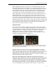
Interlaced and Progressive Video
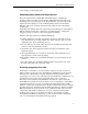
Video images consist of two interlaced fields that together comprise a frame
(see Figure 2). This approach was introduced when TV was first invented
due to a technical limitation that prevented a full frame to be “progressively”
drawn on the monitor (from top to bottom) without a noticeable visual
shuttering (as the images where being displayed it appeared as though they
were being wiped on the screen). By breaking up the image into two fields
(halves) and displaying one after the other this artifact was eliminated. This
legacy technique has been a tremendous obstacle in the digital age of video
and computers, and has been eliminated from newer video standards for
High Definition television, which are progressive (images are drawn in one
pass from top to bottom). Both interlaced groups of lines are known as a
field, and are referred to as the upper field and the lower field. Fields are
also sometimes referred to as Field 1 and Field 2, or odd and even, or top
and bottom. Unfortunately there is not a standard nomenclature.
Figure 2: Illustrating the effects of interlaced images.
With real video footage, two interlaced fields often look very similar and no
visible artifacts appear when looking at a video frame on a computer
monitor. However, with video footage that includes high motion material
that changes quickly (such as movement of the camera or of people in the
frame) very noticeable field artifacts will appear giving the image a ghosted
quality. This is due to the composition of two moments in time together in
one frame.
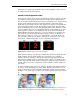
In order to display crisp video on a computer monitor video frames must be
de-interlaced by eliminating one of the fields. Half the information of each
frame is discarded and the remaining information doubled or interpolated,
in NTSC’s case giving you 30 frames of 30 distinct points in time (see Fi gure
3).
Figure 3: In this example the image on the left is an interlaced frame; in the image on
the right one of the fields has been eliminated to produce a “de-interlaced” frame.