
Installation manual


Page 20
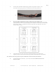
Step 11, Install Guards If Necessary
Refer to Section 2.6 on page 10 for guidelines.
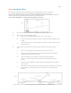
Step 12, Install Input Power
A)
B)
C)
Verify that input power voltage and number of phases match that of the MCP.
Determine the appropriate size for the input circuit by multiplying the maximum input amperage of
the VFD — found on the door of the MCP and on the included control
panel schematic (wiring diagram) — by the number of fans to be placed on the circuit. Be sure the
breakers used match the voltage of the VFD. Each MCP contains input fuses
providing individual circuit protection for each unit, but an appropriately-sized input breaker must
still be installed.
Connect a ground wire from the supply panel to the ground bar located inside of MCP.
Note: ALWAYS connect the grounding bar in the MCP to ground at the power panel — when
pulling power from the main panel, be sure to pull a full sized ground.
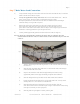
D) Connect input power leads to the proper terminals of the disconnect switch located on
the side of the MCP. Do not connect these wires directly to the VFD!
Step 13, Verify Proper Operation
Leave the door of the MCP open during this process so the front of the VFD is visible.
A)
B)
C)
D)
E)
Turn the service disconnect to the On position. When power is applied, the green On indicator
(located on the front of the VFD) will light.
Adjust the speed control knob (located on the remote switchbox) to 4.
Turn the For-Off-Rev (Forward/ Off/ Reverse) switch (located on the remote switchbox) to the For
(Forward) position.
After a 15 second delay, the fan will begin to accelerate slowly.
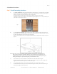
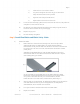
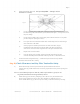
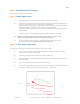
Verify proper rotation with the For-Off-Rev switch in the For position: the rotor should be turning in
the counter-clockwise direction when viewed from the floor — see figure 13.
Fig 13
P ro p
as vieer directio
wed
f r o m n o f b la d e
o u te r
end rootation
f b la d
e
MacroAir, Inc. www.macroairfans.com Toll Free: 866-668-3247 Build: March 2012