
Installation manual


Page 16
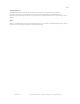
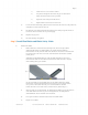
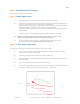
E) Twist the three uninsulated stranded copper ground wires together (see figure 7) and
connect them to the green ground screw located inside of the motor junction box.
Fig 7
F)
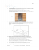
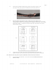
Wire motor leads for the appropriate voltage, referring to the wiring diagram on the
motor's information label/plate or to Figure 8. Note that the top four diagrams are for U.S. motors,
while the bottom two are for CE motors, usually for use outside the U.S. Be certain to wire the motor
for the correct voltage — a mistake here can ruin the motor and/or the VFD and is not covered
under the factory warranty.
Fig 8
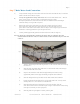
G) At the other end of the cable, twist the three uninsulated stranded copper ground wires
together (see figure 7) and connect them to the ground bar located inside of the Control Panel.
Note: ALWAYS connect the ground wire of the included motor cable at both ends, MCP and motor.
H) Connect motor leads to terminals U, V, & W on the VFD. Do not attach these leads to the
disconnect switch!
MacroAir, Inc. www.macroairfans.com Toll Free: 866-668-3247 Build: March 2012