
Installation manual


B)
C)
D)
Page 14
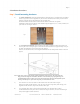
The MCP should be mounted at least 5 feet outside of the swept area of the fan blades;
this will allow safe operation of the fan and still provide access to the MCP when the fan is running.
Be sure to keep the lockable service disconnect located on the side of the MCP within line of sight
of the fan motor to comply with OSHA and local safety codes.
Mount the MCP, making sure the enclosure is firmly fixed to the mounting surface.
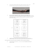
Step 5, Mount Remote Switchbox
Select a location for the remote switchbox and mount securely.
A)
B)
C)
D)
The remote switchbox should be mounted so that no more than 100 feet of remote cable is required to
connect it to the MCP.
Mount the remote switchbox in a location that is easily accessible for personnel authorized
to operate the fan.
Locate the switchbox in an area where it will be safe from damage caused by unintended
contact.
Securely mount the remote enclosure, making sure it cannot be easily detached by incidental
contact.
Step 6, Make Control Circuit Connections
A)
B)
C)
D)
E)
F)
Strip cable and conductors at both ends.
Install one supplied strain relief fitting in the remote switchbox and make appropriate connections,
referring to the control panel schematic packaged inside the MCP, the
illustration on page 28, and/or the sticker inside the remote enclosure as needed. Close up the remote
enclosure.
Install the other supplied strain relief fitting in the MCP enclosure and make control circuit
connections at the terminal strip of the VFD located inside the MCP, again referring to the
packaged control panel schematic and the illustration on page 28. Do not make any incoming
power or motor lead connections at this time.
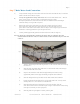
Ground the shield of the control circuit cable to the ground screw located in the lower left corner of
the VFD next to the MAINS terminal.
Daisy chain additional controllers if used, referring to the packaged control panel
schematic. Ground the shielding of the cable at the slave controller side only. There is
no need to specifically designate a "Master" drive — any drive may be used as either a
master or slave with no changes. If interfacing with any kind of automated building
management system, however, please consult factory as there may be additional programming
required.
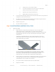
Route the control circuit cables away from all incoming power and motor cables,
keeping them separated by at least 6 inches. When control circuit wiring must cross power cables,
make sure they do so at 90 degree angles to minimize interference.
MacroAir, Inc. www.macroairfans.com Toll Free: 866-668-3247 Build: March 2012