
Installation manual


Page 12
2 Installation Procedures
Step 1, Install mounting hardware
A)
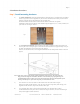
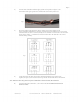
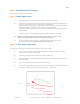
For glulam installations, attach the glulam brackets to the beam using ½" through bolts, not supplied.
Note, ½" lag screws, also not supplied, may be used as an alternative, but will not provide as much
mounting strength. Be sure the brackets line up with each other
and that the bottom of each bracket is flush with the bottom of the beam. For glulam
installations, attach the mount directly to the bracket using the supplied ½" x 2 ¾" bolts, washers, and
nylon lock nuts. See Figure 3 below.
Fig 3
B)
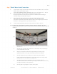
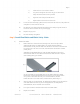
For steel I-Beam installations, mount so that the large plate is against the bottom of the beam. Be
sure the plate is at a 90 degree angle to the beam and centered. Place the supplied clamps on top of
the beam and attach them to the mount using the supplied
fasteners. For thicker I-beams, use the supplied shims between the clamp and the mount as shown in
figure 4.
Fig 4
Note: In all cases, be sure to thoroughly tighten all mounting bolts and nuts. The nylon lock nuts
help prevent loosening due to vibration, but there is no substitute for proper tightening. We
recommend that nylon lock nuts not be removed and reused because this will defeat the nylon
locking; instead, buy new nylon lock nuts from your local hardware store.
C)
D)
If an extension is to be used, attach it to the bottom of the universal mount using the
fasteners provided with the extension. Also, be sure to save the longer safety cable and guy wire
supplied with the extension; they will be needed in later steps.
Loop supplied safety cable (1/4 inch steel braided cable) over the beam and let it hang.
It will be attached once the power unit is installed. If using an extension, be sure to use the longer
safety cable supplied with the extension.
MacroAir, Inc. www.macroairfans.com Toll Free: 866-668-3247 Build: March 2012