
Specifications
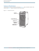
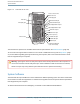
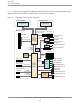
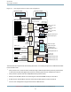

Figure 2-2 block diagram for dual 2.3 and 2.7 GHz configurations
Internal
speaker
1.5 Gbps
Serial ATA bus
10/100/1000
Ethernet port
Optical digital audio out
AirPort antenna port
400 MHz
DDR memory
bus
Processor interface bus
running at half the
processor speed
Optical digital audio in
FireWire 400 port (front)
16-bit
4.8 GBps
Hyper
Transport
8-bit
1.6 GBps
Hyper
Transport
33 MHz
PCI bus
8X AGP-Pro
slot 2.1 GBps
PCI-X slots
PMU99
power
controller
Boot
ROM
Modem slot
I2S
I2S
USB 2.0 port- (front)
480 Mbps
USB 2.0 port (rear)
480 Mbps
USB 2.0 port (rear)
480 Mbps
DIMM slots
Internal hard drive
connectors
FireWire 400 port (rear)
FireWire 800 port (rear)
Main logic board
ATA/100 bus
12 Mbps
USB
1.5 Gbps
Serial ATA bus
Internal optical
drive connector
AirPort Extreme
Card slot
K2
I/O device
and disk
controller
Headphone jack
Audio line-out port
Audio line-in port
FireWire
PHY
Audio
circuitry
Bluetooth
PCI USB
controller
100 MHz
100 MHz
133 MHz
PCI-X
bridge
Bluetooth antenna port
Processor moduleProcessor module
64-bit PowerPC G5
microprocessor
64-bit PowerPC G5
microprocessor
U3H
memory
controller
and PCI
bus bridge
The Power Mac G5 computer has the following data buses, not counting the processor’s dedicated interface
to the backside cache.
●
Dual processor bus: 1 GHz/1.15 GHz/1.35 GHz (running at half the speed of the processor), 64-bit (32-bit
in and 32-bit out) data throughput per processor connecting the processor module to the U3H IC
●
Dual processor systems have two independent 64-bit processor buses
●
Memory bus: 400 MHz, 128-bit bus connecting the main DDR SDRAM memory to the U3H IC
●
8x AGP Pro bus: 266/533 MHz, 32-bit bus connecting the AGP graphics card to the U3H IC
●
PCI bus: some configurations support three 64-bit 33 MHz PCI slots
Architecture
Block Diagram and Buses
Retired Document | 2005-04-29 | Copyright © 2003, 2005 Apple Computer, Inc. All Rights Reserved.
19