
Instruction manual

14
Alarm outputs
Connect the alarm outputs 1-2 to NC type of alarm signals, alarm outputs 3-4 to NO type
of alarm signals.
Ethernet
Connect the Ethernet connector to a standard twisted-pair Ethernet cable for remote
access via LAN or internet. Please make sure to setup the related configurations as
described in Section 6.10 Network Setup.
USB 2.0 disk drives, DVD+RW, card reader, etc.
If the user wants to use USB2.0 peripheral device to retrieve important recorded images
and/or audio, please connect it to the USB port connectors (one on the front panel, the
other on the back panel).
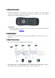
I/R remote controller
The user may use I/R remote controller to control the digital video/audio recorder.
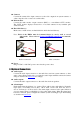
Call monitor
Connect the call monitor output connector to a surveillance CCTV monitor. This monitor
displays the full screen images of the cameras associated with the events (alarm or motion)
or the images from the installed cameras sequentially according to the SEQ Display Setup
(Section 6.4) for call monitor.
PTZ Cameras
Connect the RS-422/485 connector to PTZ camera(s) via the appropriate cable. The
system supports a variety of different PTZ cameras, including Pelco D and Samsung
SCC-641P protocol Dome. But different PTZ cameras can coexist in a system only if they
support the same protocol. Please make sure to set the PTZ ID of the camera(s) and setup
the camera (Section 6.1) and RS-422/485 (Section 6.9) accordingly. Please also make sure
to set the RS-422/RS-485 Selector Switch if you are using the RS-422/485 port.
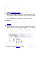
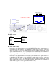
RS-485
Please refer to the following diagram for the pin definitions of the RS-422/485 connector.
Please make sure to set the RS-422/RS485 Selector Switch and setup the RS-422/485
configurations as described in Section 6.9 accordingly.