
Installation guide

31
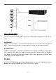
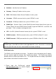
Alarm IN and OUT:
The DVR can work TTL/COMS alarm signal for the LOW & HIGH of potential or the N.O & N.C
state.
ALARM INPUT:
::
:
Support 4 ch alarm input. The extra device connects one for the alarm input, the other for
GND. Connect these connectors to external devices such as sensors or door switches.
ALARM OUTPUT:
::
:
Support 2 alarm output. Connect these connectors to 1 Normally Closed (NC) alarm outputs
and 1 Normally Open (NO) alarm outputs. Because of the DVR cannot supply any power for
extra device, you can connect the power adapter through COM to provide electric power. When
alarm trigger, the alarm output will work.
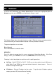
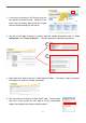
RS-485:
In SETUP SETTING Mode, press Direct Control button to change the highlighted option to
RS-485, and then press ENTER to call up RS-485 Setup as shown.