
Installation guide

23
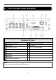
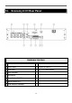
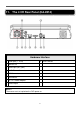
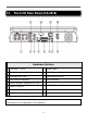
13. Image Input and Output
The DVR provides 4CH video input and output.
Video Input
Cameras connect to BNC connectors.
Monitor Output
Connect TV monitors to the BNC connector for main monitor display.
VGA
Connect VGA monitor to the VGA connector for display.
NTSC/PAL Switch
Select NTSC or PAL according to the local TV system.(adjust switch inside the main board)
NOTE:
::
:
You must select the DVR system before DVR booting. If you want to change the DVR
system, please power off the DVR first.
Network
You can view the DVR image through “IE browser” for remote control and remote recording
function. Connect this unit to a 10/100Base-T Ethernet network through this port.