
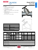
Product Overview
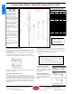

Pressure Drop Tables
- Model STVE—Sizes 8.00” to 12.00”
Optional features and accessories available for this
Macon product are an extra charge, and not included
in the standard model price.
www.maconbalancing.com
Tunstall Corporation
118 Exchange Street · Chicopee, MA 01013
Phone (413) 594-8695 · Fax (413) 598-8109
Section: Components Bulletin-MB-STVE-1016.03
CIRCUIT
SETTER
Series STVE
8.00” - 12.00”
This diagram details the
relationship between flow,
pressure drop and valve
preset points. Use the dia-
gram to select the correct
valve size and corresponding
handwheel setting to fulfill
the application requirements.
Determine the required flow
in the circuit (A) and the
pressure drop (B). Draw a
line between these two val-
ues. Read off the corre-
sponding Cv value on the Cv
scale (C).
Determine the valve setting,
in handwheel turns, by draw-
ing a horizontal line (D)
from the intersection point
on the Cv scale to the corre-
sponding valve setting posi-
tion.
For the highest level of
accuracy, it is recommended
to choose a valve that has at
least 3 open turns.
Example: A 10” valve is
required to be open 4.3 turns
for a Cv value of 500 at a
flow rate of 1300 gpm and a
pressure drop of 17 ft.
Installation Recommendations
Install the valve in the correct flow direction according to the arrow on
the valve body and the distance parameters detailed in Figure 1 (Note:
D = pipe diameter).
When used with a pump, it is recommended to use a straight length of
pipe totaling 10 x D (instead of 5 x D) upstream or downstream to
avoid turbulence that will affect the measuring accuracy. See Figure 2.
Turbulence can influence the measurements by up to 20% if this recom-
mendation is not followed.
Flow Measurement & Accuracy
The measuring instrument connects to the test ports of the valve and is
pre-programmed with Macon Balancing characteristics. The pressure
drop and flow readings can be read off the display. If access to a Macon
Balancing instrument is unavailable, other industry models are compati-
ble. In addition, the flow can be determined using the pressure drop
diagram that is included in the operating instructions with each Macon
Balancing valve.
The accuracy is highest when the valve is fully open. Therefore, it is
recommended to choose a valve that can be opened at least three turns
at the calculated pre-setting value. Figure 3 represents the flow meas-
urement deviation in relation to handwheel turns.
Correction for Liquids
Applies to liquids other than water.
Correct the measured flow (q) by the
density (Y) according to this formu-
la. See Figure 4
Sizing a Balancing Valve
When the differential pressure and
design flow are known, use this
formula to calculate Cv value. See
Figure 5
Cv Values for Valve Series STVE
Handwheel
Setting
8"
DN 200
10"
DN 250
12"
DN 300
0.5 32 50 52
1 45 72 66
1.5 53 85 83
2 63 101 104
2.5 82 134 127
3 115 189 163
3.5 172 277 234
4 250 399 383
4.5 328 522 578
5 394 628 733
5.5 448 719 848
6 497 802 954
6.5 545 881 1067
7 587 952 1177
7.5 619 1013 1272
8 648 1070 1352
8.5 682 1126 1422
9 716 1182 1486
9.5 745 1234 1549
10 771 1283 1612
10.5 796 1330 1675
11 821 1373 1739
Flow coefficient values (CV's)
at various handwheel settings
Figure 3