
Brochure
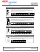
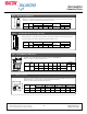
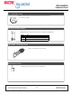
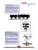
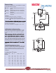
Table Of Contents
- Table of Contents
- Combined Component Submittals.pdf
- STV-STVL.pdf
- LPb - STVL & STV.pdf
- STVA.pdf
- STVC-D.pdf
- STVG.pdf
- Macon MB.pdf
- Macon MBF 2 thru 6 Submittal.pdf
- Macon MBF 8 thru 12 Submittal.pdf
- Macon VF 2.5 thru 6 Submittal.pdf
- Macon VF 8 thru 16 Submittal.pdf
- Macon VG-VW Submittal.pdf
- Macon MG Submittal.pdf
- Macon MBF-MG-VF-VG-VW Flow Chart 8_16.pdf
- Macon AB submittal.pdf
- Macon AR submittal.pdf
- Macon ABW submittal.pdf
- Macon ABG submittal.pdf
- Macon AG submittal.pdf
- Macon AW Submittal.pdf
- Macon BFV Submittal.pdf
- Macon SV Submittal.pdf
- Macon ST Submittal.pdf
- Macon SVF Submittal.pdf
- Macon SF Submittal.pdf
- Macon SG Submittal.pdf
- Macon SB Submittal.pdf
- Macon URP Submittal.pdf
- Macon US Submittal.pdf
- Macon UB Submittal.pdf
- Macon BB Submittal.pdf
- Macon GF Submittal.pdf
- Macon Tail Piece Data Chart.pdf
- Macon FH Submittal.pdf
- Macon Balancing 841 Test Kit.pdf
- Macon Balancing PFM-2000.pdf
- Accessories Submittal (1).pdf
- Accessories Submittal (2).pdf
- Accessories Submittal (3).pdf
- Pressure Differential Regulator
- Circuit Setter Valve Packages
- Automatic Balancing Valve Packages
- 2RS-AB.pdf
- 2RS-AB-FLEX.pdf
- 2RSX-AB-FLEX.pdf
- 2SS-AB.pdf
- 2SS-AB-FLEX.pdf
- 2SS-2AB.pdf
- 2SSX-AB-FLEX.pdf
- 2RB-AB.pdf
- 2SB-AB.pdf
- XXS-AB.pdf
- XXS-AB-FLEX.pdf
- XXB-AB.pdf
- ABW with SVF _WB_.pdf
- AW with SVF.pdf
- 3BV-AB.pdf
- 3RS-AB.pdf
- 3RS-AB2.pdf
- 3RS-ABX.pdf
- 3RS-ABX with T.pdf
- 3RS-ABX-FLEX with T.pdf
- 3RS-ABX-FLEX.pdf
- 3RS-ABX-FLEX-CRAC with T.pdf
- 3RB-AB.pdf
- 3RU-AB.pdf
- 3SW-AB.pdf
- 2RS-BB-FLEX.pdf
- MV Packages Combined
- Installation & Operation
- Guide Specifications
- Blank Page
- Blank Page

We reserve the right to alter information without notice.
Dimensioning
Selecting the right valve in an installation requires
some data about the system.
P pump available differential pressure from
pump
P load differential pressure for circulation
P STVP pressure drop over valve fully open
(diagram)
P PVM pressure drop over the PVM valve
(diagram)
Example:
Calculated value for a valve is 6.34 gpm.
7.25 psi is available differential pressure for
circulation P load 2.9 psi is required for the main.
for the PVM valve to achieve minimum working
pressure in the diagram.
Two valves can deliver 6.34 gpm 1” and 1 1/4”.
C 5044
DN 25
PN 20
H
P
L
Last
P+
P-
Pf
C 5044
DN 25
PN 20
P
Last
P
Pump
P
STV
P
PVM
cv-value the STV valve
Number 1/2” 3/4” 1” 1 1/4” 1 1/2” 2”
of turns
1 0.21 0.39 0.55 0.91 1.39 2.31
2 0.37 0.69 0.89 1.53 2.37 4.16
3 0.52 0.96 1.19 2.08 3.24 6.01
4 0.72 1.31 1.73 3.12 4.74 8.79
5 0.99 1.79 2.66 4.74 7.17 13.76
6 1.35 2.43 4.16 6.82 10.29 19.31
7 1.87 3.35 5.78 9.02 13.87 24.51
8 2.95 4.45 7.51 11.21 16.99 28.90
9 3.64 5.20 9.13 13.30 19.77 33.06
10 4.10 5.90 10.17 15.14 22.54 36.42
Adjustment and measuring
When adjusting, the differential pressure on the
PVM valve is measured and adjusted to 10 kPa.
At least one radiator valve needs to be slightly
open.
and a measuringtool. To be able to measure the
have a higher differential pressure over the STV
valve. Note that the differential pressure over the
STV valve will not be to high so that the min dif-
ferential pressure over the PVM valve will be to
low and the PVM valve stop to regulate. After the
again.
Optimising pump pressure
Lowering to minimum possible pump differential
pressure is carried out by measuring at the PVM
valve and obtaining at least 1.91 psi, this is the
pump’s lowest level at which the PVM can be
regulated.
Tunstall Corporation
118 Exchange Street Chicopee, MA 01013
Phone: (413) 594-8695 Fax: (413) 598-8109
www.tunstall-inc.com
.
.
R
March 2014