
Brochure
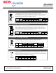
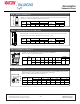
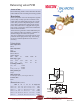
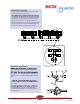
Table Of Contents
- Table of Contents
- Combined Component Submittals.pdf
- STV-STVL.pdf
- LPb - STVL & STV.pdf
- STVA.pdf
- STVC-D.pdf
- STVG.pdf
- Macon MB.pdf
- Macon MBF 2 thru 6 Submittal.pdf
- Macon MBF 8 thru 12 Submittal.pdf
- Macon VF 2.5 thru 6 Submittal.pdf
- Macon VF 8 thru 16 Submittal.pdf
- Macon VG-VW Submittal.pdf
- Macon MG Submittal.pdf
- Macon MBF-MG-VF-VG-VW Flow Chart 8_16.pdf
- Macon AB submittal.pdf
- Macon AR submittal.pdf
- Macon ABW submittal.pdf
- Macon ABG submittal.pdf
- Macon AG submittal.pdf
- Macon AW Submittal.pdf
- Macon BFV Submittal.pdf
- Macon SV Submittal.pdf
- Macon ST Submittal.pdf
- Macon SVF Submittal.pdf
- Macon SF Submittal.pdf
- Macon SG Submittal.pdf
- Macon SB Submittal.pdf
- Macon URP Submittal.pdf
- Macon US Submittal.pdf
- Macon UB Submittal.pdf
- Macon BB Submittal.pdf
- Macon GF Submittal.pdf
- Macon Tail Piece Data Chart.pdf
- Macon FH Submittal.pdf
- Macon Balancing 841 Test Kit.pdf
- Macon Balancing PFM-2000.pdf
- Accessories Submittal (1).pdf
- Accessories Submittal (2).pdf
- Accessories Submittal (3).pdf
- Pressure Differential Regulator
- Circuit Setter Valve Packages
- Automatic Balancing Valve Packages
- 2RS-AB.pdf
- 2RS-AB-FLEX.pdf
- 2RSX-AB-FLEX.pdf
- 2SS-AB.pdf
- 2SS-AB-FLEX.pdf
- 2SS-2AB.pdf
- 2SSX-AB-FLEX.pdf
- 2RB-AB.pdf
- 2SB-AB.pdf
- XXS-AB.pdf
- XXS-AB-FLEX.pdf
- XXB-AB.pdf
- ABW with SVF _WB_.pdf
- AW with SVF.pdf
- 3BV-AB.pdf
- 3RS-AB.pdf
- 3RS-AB2.pdf
- 3RS-ABX.pdf
- 3RS-ABX with T.pdf
- 3RS-ABX-FLEX with T.pdf
- 3RS-ABX-FLEX.pdf
- 3RS-ABX-FLEX-CRAC with T.pdf
- 3RB-AB.pdf
- 3RU-AB.pdf
- 3SW-AB.pdf
- 2RS-BB-FLEX.pdf
- MV Packages Combined
- Installation & Operation
- Guide Specifications
- Blank Page
- Blank Page

C
50
44
D
N
2
5
PN 20
C
50
44
DN
25
P
N
20
C
5
0
4
4
D
N
25
P
N
2
0
C
5
0
4
4
D
N
25
PN
20
C
5
0
4
4
D
N 25
PN 20
C
5
0
4
4
D
N 25
PN 20
C
504
4
DN
2
5
PN
20
The critical point
C 5044
DN 25
PN 20
P+
P-
Pf
1
2
3
Standard application
to be connected at the low pressure side of the
of whether it is a straight length of pipe. Bends,
tubes etc. can be installed immediately after the
valve.
2. Install t-pipe with measurement socket on the
STV valve.
ensure that there is no air in the signal pipe.
4. Install the signal pipe on the PVM valve on
the return pipe.
Installation example
Overview of a heating system with 5 staircases
with 4 apartments on each one.
lowest pressure drop as a rule of thumb this will
be the valve positioned furthest away from the
pump, is used to lower the pump pressure so
that the valve achieves the correct pressure. The
lowest possible pressure is then obtained in the
system. See dimensioning pump pressure.
Tunstall Corporation
118 Exchange Street Chicopee, MA 01013
Phone: (413) 594-8695 Fax: (413) 598-8109
www.tunstall-inc.com
.
.
R
March 2014