
Brochure
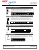
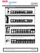
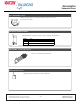
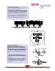
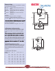
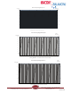
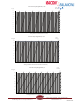
Table Of Contents
- Table of Contents
- Combined Component Submittals.pdf
- STV-STVL.pdf
- LPb - STVL & STV.pdf
- STVA.pdf
- STVC-D.pdf
- STVG.pdf
- Macon MB.pdf
- Macon MBF 2 thru 6 Submittal.pdf
- Macon MBF 8 thru 12 Submittal.pdf
- Macon VF 2.5 thru 6 Submittal.pdf
- Macon VF 8 thru 16 Submittal.pdf
- Macon VG-VW Submittal.pdf
- Macon MG Submittal.pdf
- Macon MBF-MG-VF-VG-VW Flow Chart 8_16.pdf
- Macon AB submittal.pdf
- Macon AR submittal.pdf
- Macon ABW submittal.pdf
- Macon ABG submittal.pdf
- Macon AG submittal.pdf
- Macon AW Submittal.pdf
- Macon BFV Submittal.pdf
- Macon SV Submittal.pdf
- Macon ST Submittal.pdf
- Macon SVF Submittal.pdf
- Macon SF Submittal.pdf
- Macon SG Submittal.pdf
- Macon SB Submittal.pdf
- Macon URP Submittal.pdf
- Macon US Submittal.pdf
- Macon UB Submittal.pdf
- Macon BB Submittal.pdf
- Macon GF Submittal.pdf
- Macon Tail Piece Data Chart.pdf
- Macon FH Submittal.pdf
- Macon Balancing 841 Test Kit.pdf
- Macon Balancing PFM-2000.pdf
- Accessories Submittal (1).pdf
- Accessories Submittal (2).pdf
- Accessories Submittal (3).pdf
- Pressure Differential Regulator
- Circuit Setter Valve Packages
- Automatic Balancing Valve Packages
- 2RS-AB.pdf
- 2RS-AB-FLEX.pdf
- 2RSX-AB-FLEX.pdf
- 2SS-AB.pdf
- 2SS-AB-FLEX.pdf
- 2SS-2AB.pdf
- 2SSX-AB-FLEX.pdf
- 2RB-AB.pdf
- 2SB-AB.pdf
- XXS-AB.pdf
- XXS-AB-FLEX.pdf
- XXB-AB.pdf
- ABW with SVF _WB_.pdf
- AW with SVF.pdf
- 3BV-AB.pdf
- 3RS-AB.pdf
- 3RS-AB2.pdf
- 3RS-ABX.pdf
- 3RS-ABX with T.pdf
- 3RS-ABX-FLEX with T.pdf
- 3RS-ABX-FLEX.pdf
- 3RS-ABX-FLEX-CRAC with T.pdf
- 3RB-AB.pdf
- 3RU-AB.pdf
- 3SW-AB.pdf
- 2RS-BB-FLEX.pdf
- MV Packages Combined
- Installation & Operation
- Guide Specifications
- Blank Page
- Blank Page

Setting
The valve is easy to set on the knob using a 4 mm
Allen key. The setting is read off the pressure
drop diagram for each dimension.
When presetting the valve, start by screwing the
setting to minimum. Then open the valve to the
required value according to the diagram.
The STV valve is used solely for shutting off and
-
tion other than open.
Higher
p
Lower
p
Presetting
The PVM valve is preset according to the
diagram.
The curves (the oblique lines that indicate the
pressure in the main line) are shown in intervals
of 0.73 psi to make it simple to take a reading. The
curves can be moved so that the valve setting can
be produced if, for example, 1.74 psi is selected in
a pipe instead.
Example: We decide to maintain 1.74 psi diffe-
(2.2 gpm comes from the presetting on the
radiators).
From the point where 1.74 psi cuts the horizontal
to the x-axis.
It is then easy to read off that the valve should be
set at approx. 7 turns. The minimum pressure drop
will then be 0.28 psi over the valve.
Total pressure drop:
To dimension the pump it will be:
P = Ps + Pv = 1.74 +0.28 = 2.02 psi
Also include the pipe pressure drop from the
valve to the pump.
The pump can subsequently be adjusted optimally
by measuring the differential pressure from PF to
P- ( P pump). To verify the secondary pressure
drop calculated, it can be checked by measuring
PF to P+ and the result should then be 1.74 psi.
Tunstall Corporation
118 Exchange Street Chicopee, MA 01013
Phone: (413) 594-8695 Fax: (413) 598-8109
www.tunstall-inc.com
.
.
R
March 2014
rential pressure in the main at a flow of 2.2 gpm
line (flow 2.2 gpm) a vertical line is taken down