
Brochure

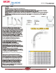
Table Of Contents
- Table of Contents
- Combined Component Submittals.pdf
- STV-STVL.pdf
- LPb - STVL & STV.pdf
- STVA.pdf
- STVC-D.pdf
- STVG.pdf
- Macon MB.pdf
- Macon MBF 2 thru 6 Submittal.pdf
- Macon MBF 8 thru 12 Submittal.pdf
- Macon VF 2.5 thru 6 Submittal.pdf
- Macon VF 8 thru 16 Submittal.pdf
- Macon VG-VW Submittal.pdf
- Macon MG Submittal.pdf
- Macon MBF-MG-VF-VG-VW Flow Chart 8_16.pdf
- Macon AB submittal.pdf
- Macon AR submittal.pdf
- Macon ABW submittal.pdf
- Macon ABG submittal.pdf
- Macon AG submittal.pdf
- Macon AW Submittal.pdf
- Macon BFV Submittal.pdf
- Macon SV Submittal.pdf
- Macon ST Submittal.pdf
- Macon SVF Submittal.pdf
- Macon SF Submittal.pdf
- Macon SG Submittal.pdf
- Macon SB Submittal.pdf
- Macon URP Submittal.pdf
- Macon US Submittal.pdf
- Macon UB Submittal.pdf
- Macon BB Submittal.pdf
- Macon GF Submittal.pdf
- Macon Tail Piece Data Chart.pdf
- Macon FH Submittal.pdf
- Macon Balancing 841 Test Kit.pdf
- Macon Balancing PFM-2000.pdf
- Accessories Submittal (1).pdf
- Accessories Submittal (2).pdf
- Accessories Submittal (3).pdf
- Pressure Differential Regulator
- Circuit Setter Valve Packages
- Automatic Balancing Valve Packages
- 2RS-AB.pdf
- 2RS-AB-FLEX.pdf
- 2RSX-AB-FLEX.pdf
- 2SS-AB.pdf
- 2SS-AB-FLEX.pdf
- 2SS-2AB.pdf
- 2SSX-AB-FLEX.pdf
- 2RB-AB.pdf
- 2SB-AB.pdf
- XXS-AB.pdf
- XXS-AB-FLEX.pdf
- XXB-AB.pdf
- ABW with SVF _WB_.pdf
- AW with SVF.pdf
- 3BV-AB.pdf
- 3RS-AB.pdf
- 3RS-AB2.pdf
- 3RS-ABX.pdf
- 3RS-ABX with T.pdf
- 3RS-ABX-FLEX with T.pdf
- 3RS-ABX-FLEX.pdf
- 3RS-ABX-FLEX-CRAC with T.pdf
- 3RB-AB.pdf
- 3RU-AB.pdf
- 3SW-AB.pdf
- 2RS-BB-FLEX.pdf
- MV Packages Combined
- Installation & Operation
- Guide Specifications
- Blank Page
- Blank Page

GUIDE SPECIFICATIONS – MANUAL VENTURI BALANCING VALVES
MANUFACTURER
1. Macon Balancing, Models MB or MBF
DESIGN
1. Flow devises shall be Venturi type as
recommended by ASHRAE.
2. Devices shall have a precision-machined
throat and have a stated catalog accuracy of
3% of flow rate.
3. MINIMUM GAUGE READING:
The gauge reading (flow signal) shall be at least
two feet at the design flow with the valve in the
wide open position.
4. The valves are to have differential readout
ports fitted with check valve and protective cap,
and are to have a memory stop to allow complete
shut-off and return to set position with out losing
the set point.
5. PUMP HEAD REQUIREMENTS:
The permanent pressure loss added to the pump
head shall not exceed two feet, per device, at the
design GPM in the wide-open position.
CONSTRUCTION
1. All devices shall have a Venturi section and
a throttling valve with a memory stop on the
downstream side of the Venturi.
2. Sizes .50" - 2.0" shall have a brass alloy body
with sweat or threaded (NPT) connections, ball
valve shall have a plated brass ball, blowout-proof
brass stem, union end which will except various
type tailpieces, Teflon seat, EPDM o-ring seals,
and a steel handle.
Sizes 2.5" – 6" shall have a cast steel body.
Flanges shall be compatible with ANSI
B16.5-1968 150lb. Butterfly Valve shall be ductile
iron lug type, with EPDM seats, 416 SS stem,
Teflon bushing, aluminum/bronze disc.
3. All valves .50" – 2.0" shall be factory leak
tested at 100PSI air under water.
MINIMUM RATINGS
1. Devises with sweat or NPT connections
.50" – 2" : 400 PSIG @ 250°F.
2. Devises with Flanged connections
2" – 10" : 200 PSIG @ 250°F.
READOUT METER KIT
Provide a portable readout meter kit by the
manufacturer of the balancing devices.
1. The meter shall be housed in a durable case
complete with two 10’ color coded hoses with
shut-off valves at the end that connects to the
balancing valve so that water does not drain out
between readings.
2. Meter shall have a 6" diameter face and ±1.75%
full-scale accuracy.
3. Meter shall have a forged brass body and a
three-valve manifold for over-range protection.
4. Meter shall have a dual scale reading inches
and feet W.C.
INSTALLATION
1. The straight pipe required to achieve 3% F.S.
accuracy shall be incorporated as an integral part
of the .50" to 2" valve assembly. Five pipe
diameters of straight pipe are required from a
control valve for sizes 2.5" – 10".
2. Install balancing valves on the return lines of the
coil as recommended by ASHRAE.
3. Install in accordance with the manufacturer’s
instructions.
Form # GS-MV-03.14
Tunstall Corporation
118 Exchange Street
Chicopee, MA 01013