
Brochure

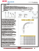
Table Of Contents
- Table of Contents
- Combined Component Submittals.pdf
- STV-STVL.pdf
- LPb - STVL & STV.pdf
- STVA.pdf
- STVC-D.pdf
- STVG.pdf
- Macon MB.pdf
- Macon MBF 2 thru 6 Submittal.pdf
- Macon MBF 8 thru 12 Submittal.pdf
- Macon VF 2.5 thru 6 Submittal.pdf
- Macon VF 8 thru 16 Submittal.pdf
- Macon VG-VW Submittal.pdf
- Macon MG Submittal.pdf
- Macon MBF-MG-VF-VG-VW Flow Chart 8_16.pdf
- Macon AB submittal.pdf
- Macon AR submittal.pdf
- Macon ABW submittal.pdf
- Macon ABG submittal.pdf
- Macon AG submittal.pdf
- Macon AW Submittal.pdf
- Macon BFV Submittal.pdf
- Macon SV Submittal.pdf
- Macon ST Submittal.pdf
- Macon SVF Submittal.pdf
- Macon SF Submittal.pdf
- Macon SG Submittal.pdf
- Macon SB Submittal.pdf
- Macon URP Submittal.pdf
- Macon US Submittal.pdf
- Macon UB Submittal.pdf
- Macon BB Submittal.pdf
- Macon GF Submittal.pdf
- Macon Tail Piece Data Chart.pdf
- Macon FH Submittal.pdf
- Macon Balancing 841 Test Kit.pdf
- Macon Balancing PFM-2000.pdf
- Accessories Submittal (1).pdf
- Accessories Submittal (2).pdf
- Accessories Submittal (3).pdf
- Pressure Differential Regulator
- Circuit Setter Valve Packages
- Automatic Balancing Valve Packages
- 2RS-AB.pdf
- 2RS-AB-FLEX.pdf
- 2RSX-AB-FLEX.pdf
- 2SS-AB.pdf
- 2SS-AB-FLEX.pdf
- 2SS-2AB.pdf
- 2SSX-AB-FLEX.pdf
- 2RB-AB.pdf
- 2SB-AB.pdf
- XXS-AB.pdf
- XXS-AB-FLEX.pdf
- XXB-AB.pdf
- ABW with SVF _WB_.pdf
- AW with SVF.pdf
- 3BV-AB.pdf
- 3RS-AB.pdf
- 3RS-AB2.pdf
- 3RS-ABX.pdf
- 3RS-ABX with T.pdf
- 3RS-ABX-FLEX with T.pdf
- 3RS-ABX-FLEX.pdf
- 3RS-ABX-FLEX-CRAC with T.pdf
- 3RB-AB.pdf
- 3RU-AB.pdf
- 3SW-AB.pdf
- 2RS-BB-FLEX.pdf
- MV Packages Combined
- Installation & Operation
- Guide Specifications
- Blank Page
- Blank Page

GUIDE SPECIFICATIONS – STVL / STV / STVA / STVC BALANCING VALVES
TYPICAL SPECIFICATION
All balancing valves shall be of one manufacturer.
Furnish and install, as shown on job plans and in accordance with manufacturers installation instructions,
Macon Balancing Valves, Series STVL/STV/STVA/STVC. Valves are to be of “Y” pattern globe style
design and perform the following functions: a) Flow balancing, b) Flow measurement, c) Positive shut-off.
All balancing valves must have a minimum ten (10) turn, 360° handwheel with digital and vernier scale
readout for precise setting. Balancing handwheel must include a memory stop and locking feature to prevent
tampering after pre-setting.
All balancing valves shall have self-sealing ports for measurement of differential pressure and fluid
temperature using standard pressure and temperature test probes. Test ports shall be located at a 45°
offsetting angle and be removable for implementation of optional drain kits where required.
All balancing valves in sizes 1/2” (DN 15) through 2” (DN 50) shall be made of dezincification resistant
brass and have either sweat or NPT thread connections. Valve body sizes 2 1/2” (DN 65) through 12”
(DN 300) shall be made of cast iron and flanged to 125 lb standard.
All balancing valves shall be manufactured by the company complying with international quality
standard ISO 9001.
Form # GS-GLOBE-03.14
Tunstall Corporation
118 Exchange Street
Chicopee, MA 01013