
Brochure
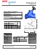
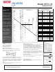
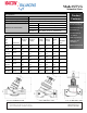
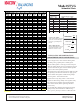
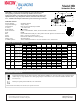
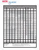
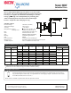
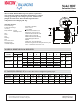
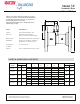
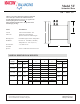
Table Of Contents
- Table of Contents
- Combined Component Submittals.pdf
- STV-STVL.pdf
- LPb - STVL & STV.pdf
- STVA.pdf
- STVC-D.pdf
- STVG.pdf
- Macon MB.pdf
- Macon MBF 2 thru 6 Submittal.pdf
- Macon MBF 8 thru 12 Submittal.pdf
- Macon VF 2.5 thru 6 Submittal.pdf
- Macon VF 8 thru 16 Submittal.pdf
- Macon VG-VW Submittal.pdf
- Macon MG Submittal.pdf
- Macon MBF-MG-VF-VG-VW Flow Chart 8_16.pdf
- Macon AB submittal.pdf
- Macon AR submittal.pdf
- Macon ABW submittal.pdf
- Macon ABG submittal.pdf
- Macon AG submittal.pdf
- Macon AW Submittal.pdf
- Macon BFV Submittal.pdf
- Macon SV Submittal.pdf
- Macon ST Submittal.pdf
- Macon SVF Submittal.pdf
- Macon SF Submittal.pdf
- Macon SG Submittal.pdf
- Macon SB Submittal.pdf
- Macon URP Submittal.pdf
- Macon US Submittal.pdf
- Macon UB Submittal.pdf
- Macon BB Submittal.pdf
- Macon GF Submittal.pdf
- Macon Tail Piece Data Chart.pdf
- Macon FH Submittal.pdf
- Macon Balancing 841 Test Kit.pdf
- Macon Balancing PFM-2000.pdf
- Accessories Submittal (1).pdf
- Accessories Submittal (2).pdf
- Accessories Submittal (3).pdf
- Pressure Differential Regulator
- Circuit Setter Valve Packages
- Automatic Balancing Valve Packages
- 2RS-AB.pdf
- 2RS-AB-FLEX.pdf
- 2RSX-AB-FLEX.pdf
- 2SS-AB.pdf
- 2SS-AB-FLEX.pdf
- 2SS-2AB.pdf
- 2SSX-AB-FLEX.pdf
- 2RB-AB.pdf
- 2SB-AB.pdf
- XXS-AB.pdf
- XXS-AB-FLEX.pdf
- XXB-AB.pdf
- ABW with SVF _WB_.pdf
- AW with SVF.pdf
- 3BV-AB.pdf
- 3RS-AB.pdf
- 3RS-AB2.pdf
- 3RS-ABX.pdf
- 3RS-ABX with T.pdf
- 3RS-ABX-FLEX with T.pdf
- 3RS-ABX-FLEX.pdf
- 3RS-ABX-FLEX-CRAC with T.pdf
- 3RB-AB.pdf
- 3RU-AB.pdf
- 3SW-AB.pdf
- 2RS-BB-FLEX.pdf
- MV Packages Combined
- Installation & Operation
- Guide Specifications
- Blank Page
- Blank Page

PRESSURE DROP TABLES
Series STVC-D,
8” - 12”
This diagram details the
relationship between flow,
pressure drop and valve
preset points. Use the
diagram to select the
correct valve size and
corresponding handwheel
setting to fulfill the
application requirements.
Determine the requi red
flow in the circuit (A) and
the pressure drop (B).
Draw a line between these
two values. Read off the
corresponding Cv value on
the Cv scale (C).
Determine the valve
setting, in handwheel
turns, by drawing a
horizontal line (D) from
the i ntersection point on
the Cv scale to the
corresponding valve
setting position.
For the highest lev el of
accuracy, it is recom-
mended to choose a valve
that has at least 3 open
turns.
Example: a 10” valve is
required to be open 8 turns
for a Cv value of 890 at a
flow rate of 1000 gpm and a
pressure drop of 3 ft.
Flow Measurement & Accuracy
The measuring instrument connects to the test ports of the valve and
is pre-programmed with Macon Balancing characteristics. The
pressure drop and flow readings can be read off the display. If
access to a Macon Balancing instrument is unavailable, other industry
standard models are compatible. In addition, the flow can be
determined using the pressure drop diagram that is included in the
operating instructions with each Macon Balancing valve.
The accuracy is highest when the valve is fully open. Therefore, it is
recommended to choose a valve that can be opened at least three
turns at the calculated pre-setting value. Figure 3 represents the flow
measurement deviation in relation to handwheel turns.
Correction For Liquids
Applies to liquids other than water. Correct the measured flow (q) by
the density (γ) according to this formula.
Sizing a Balancing V alve
When the differential pressure and design flow are known, use this
formula to calculate Cv value.
Installation Recommendations
Install the valve in the correct flow direction according to the
arrow on the valve body and the distance parameters detailed
in Figure 1 (Note: D = pipe diameter).
Cv Valu es for Valve Series STVC-D
Figure 1
D
D1
5 x D
2 x D
For Series S TVC-D, cover the valve body with a wet cloth when
soldering to prevent premature deterioration of valve components.
When used with a pump, it is recommended to use a straight length
of pipe totaling 10 x D (instead of 5 x D) upstream or downstream
to avoid turbulence that will affect the measuring accuracy. See
Figure 2.
Turbulence can influence the measurements by up to 20% if this
recommendation is not followed.
Actual Flow =
qCBI
C
v
= 1.52
q
q in GPM, p in Ft. of H2O
C
v
=
q
q in GPM, p in PSI
√
γ
Δ
√
p
√
p
√
Δ
Δ
Flow coefficient values (Cv's)
at various handwheel settings
Handwheel
Setting
8"
DN 200
10"
DN 250
12"
DN 300
1 55 74 85
2 88 112 144
3 122 147 203
4 153 188 262
5 186 230 321
6 218 269 380
7 249 305 429
8 282 348 477
9 313 385 541
10 343 426 603
11 379 464 640
12 412
519
677
13 443
544
715
14 478 587 752
B
C
D
A
Model STVC-D
Submittal Data
15 512
625
789
16 553 664 889
17 601
705
988
18
641
749 1,089
19
684
793 1,189
20 836 1,289
728
21 775 884 1,340
22 820 937 1,391
23 870
984
1,442
24 916
1,034
1,493
25 957 1,079 1,544
26 1,006
1,138
1,604
27 1,056 1,196 1,666
28 1,250 1,726
29 1,306 1,786
30 1,361 1,847
31 1,412 1,891
32 1,458 1 ,935
33 1,510 1 ,978
33.3 1,993
Figure 3
Pre setting
-
-
-
-
-
-
-
-
Deviation +/%
1
2
3
4
5
6 7
8
9 10
2
4
6
8
10
12
14
16
Form # STVC-D-03.14
Optional features and accessories available
for this Macon product are an extra charge,
and not included in the standard model price.
Tunstall Corporation
118 Exchange Street
Chicopee, MA 01013