
User`s guide


Using the IOMUX Design Aid
i.MX53 System Development User’s Guide, Rev. 1
Freescale Semiconductor 4-17
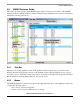
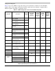
The following list explains each column’s function:
Peripheral/Signal This column contains the peripheral and signal names, delimited by the first
underscore in the name. The naming convention comes from the Excel
spreadsheets that have previously been used to manually make IOMUX
assignments.
ALT-Mode/Ball This column contains the ALT-mode and package ball/pin assigned to each signal,
separated by a hyphen. In the application code, the IOMUX register for the
assigned ball/pin needs to be configured with the ALT-mode specified in the
assignment. It should be noted that a SW_INPUT_SELECT register may also
need to be assigned, depending on the signal (refer to the device’s reference
manual).
GPIO This column is a handy reference for the hardware bring-up team for testing basic
connectivity without having to actually set up the assigned signals as intended in
the application.
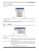
Signal Notes This column provides a means of annotating the specific signal assignments.
Signal notes are added by right-clicking on an assignment row. Any information
that the user feels is relevant may be inserted in the text box that pops up.
Consider placing information that is helpful for other people that review the
schematics in addition to information helpful for software developers. The output
of this tool can be pasted into both the schematic files as well as the application
source code.
Shared Signals This column shows all of the other signals available to be muxed out on the
assigned ball/pin. This information is identical to the information available by
hovering the mouse over an assignment row in the same pane.
NOTE
The signal notes column and shared signals column cannot be viewed
simultaneously.
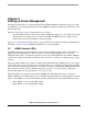
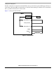
4.5.5.2 Ball Diagram Tab
The ball diagram tab provides a visual indication of where assigned signals enter or exit the device
package. Each ball or pin is color coded according to a legend at the bottom of the pane (see Figure 4-10).
Hovering over a ball/pin brings up a pop-up that contains a list of available internal signals that may be
assigned to that ball/pin for those package interconnects that the IOMUX controls. Note that dedicated
signals, power, and ground connections are not shown; refer to the device’s data sheet for complete
package connection information.
4.5.6 Status Bar
The status bar is located at the bottom of the application window. On its left side, it indicates the device
selected for the design and a count of the assigned and total signals available to the IOMUX for that
design’s device. On the right side, it shows a count of the conflicting assignments.