
User`s guide

Using the IOMUX Design Aid
i.MX53 System Development User’s Guide, Rev. 1
4-6 Freescale Semiconductor
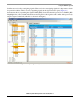
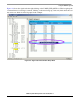
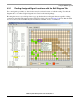
In this example, the conflicts are resolved by assigning V13 to UART3_RXD_MUX and T13 to
UART3_TXD, as shown in Figure 4-5. Notice that the original ball assignments for these two signals are
now highlighted in yellow, which indicates that conflicts exist if the signals are assigned to those balls. All
the conflicts in our example have now been resolved.
Figure 4-5. Resolving Conflicts by Changing Ball Assignments
NOTE
In an actual design, several iterations of re-assigning balls for signals may
be required to resolve all the conflicts for chosen signals. In this example,
all signals for each peripheral group were selected by checking the box next
to the peripheral. In actual usage, only a subset of all the signals for a
peripheral are selected.
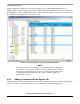
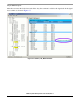
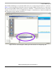
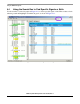
4.2.2 Adding Comments with the Signals Tab
Adding information to the pin assignments allows users to explain why selections are made, what the pins
connect to, and how they are intended to be used. Comments are added in the signals tab.