
User`s guide

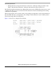


Using the IOMUX Design Aid
i.MX53 System Development User’s Guide, Rev. 1
4-2 Freescale Semiconductor
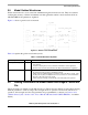
4.2.1 Identifying Signal Conflicts with the Signal Selection Pane
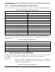
Figure 4-1 shows the application window after the following sequence:
1. Launch IOMux.exe application.
2. Select Device > i.MX35 TO2.1.
3. Check all UARTS (UART1, UART2, and UART3).
4. Expand the signals UART3_RXD_MUX and UART3_TXD_MUX.
Figure 4-1. Application Window after Expanding UARTs 2 and 3 of i.MX35 TO2.1
The orange highlighting in the signal selection pane indicates conflicts between signals. This example
shows four specific conflicts (marked by purple lines in the figure). The conflicts were detected
immediately after selecting the second UART because the auto-detect conflicts option is enabled by
default when the application starts up. Peripheral groups expand to show the conflicts at the signal level
once they are detected. The status bar shows the exact number of conflicting signals in the lower right
corner of the application window.
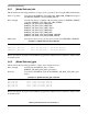
To see what other signals share the assigned ball for a signal, hover the mouse over a signal. Figure 4-2
illustrates this, using the UART3_TXD_MUX signal as an example. Note that UART2_CTS, which is one
of the four conflicts highlighted in orange, is also bolded in the UART3_TXD_MUX pop-up list. The