
User`s guide

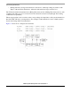


Understanding the IBIS Model
i.MX53 System Development User’s Guide, Rev. 1
3-10 Freescale Semiconductor
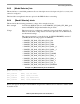
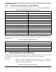
3.6.5 List of Pins Not Modeled in the i.MX53 IBIS File
Table 3-5 provides a list of analog or special interface pins that are not modeled in the i.MX53 IBIS file:
Table 3-6 provides a list of differential signals that are not represented in the current IBIS file. These
signals require special treatment to be considered during PCB design. Complementary signals are shown
in the same row.
3.7 Quality Assurance for the IBIS Models
The IBIS models are validated against the IBIS specification, which provides a way to objectively measure
the correlation of model simulation results with reference transistor-level spice simulation or
measurements.
Correlation The process of making a quantitative comparison between two sets of I/O buffer
characterization data, e.g. lab measurement vs. structural simulation or behavioral
simulation vs. Structural simulation.
Table 3-5. Unmodeled Analog or Special Interface Pins
Pin Name
CKIL TVDAC_COMP
ECKIL TVDAC_IOB
EXTAL TVDAC_IOG
XTAL TVDAC_IOR
CKIH1 TVDAC_VREF
CKIH2 USB_H1_GPANAIO
DRAM_CALIBRATION USB_H1_RREFEXT
FASTR_ANA USB_H1_VBUS
FASTR_DIG USB_OTG_GPANAIO
LVDS_BG_RES USB_OTG_ID
TVCDC_IOB_BACK USB_OTG_RREFEXT
TVCDC_IOG_BACK USB_OTG_VBUS
TVCDC_IOR_BACK SATA_REXT
Table 3-6. Unmodeled Differential Signals
Differential Signal Name
SATA_TXM SATA_TXP
SATA_RXM SATA_RXP
SATA_REFCLKM SATA_REFCLKP
USB_H1_DN USB_H1_DP
USB_OTG_DN USB_OTG_DP