
User`s guide

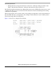


Understanding the IBIS Model
i.MX53 System Development User’s Guide, Rev. 1
Freescale Semiconductor 3-9
3.6.3 [Model Selector] lvio
This model has no controllable parameters. Its associated pins are used as input only (for boot, reset) and
cannot be configured.
The listed drive strength and slew rate options in the IBIS file have no meaning.
3.6.4 [Model Selector] uhvio
This model has the following parameters: voltage, drive strength, slew rate.
Drive strength Controlled by DSE bits (bits 2-1) in the IOMUXC_SW_PAD_CTL_PAD_<pad
name> in IOMUXC chapter that matches the pin name.
Voltage The pin needs to be configured to match the voltage level that is supplied to it.
There is an automatic voltage detection for these pins, but it is recommended to
use the manual settings.
The voltage parameter is controlled by bit 18 (HVEOVERWRITE) and bit 17
(VDOEN) in the following registers in IOMUXC:
• IOMUXC_SW_PAD_CTL_PAD_NVCC_SD1
• IOMUXC_SW_PAD_CTL_PAD_NVCC_SD2
• IOMUXC_SW_PAD_CTL_PAD_NVCC_GPIO
• IOMUXC_SW_PAD_CTL_PAD_NVCC_PATA__0
• IOMUXC_SW_PAD_CTL_PAD_NVCC_PATA__2
• IOMUXC_SW_PAD_CTL_PAD_NVCC_FEC
• IOMUXC_SW_PAD_CTL_PAD_NVCC_NANDF
• IOMUXC_SW_PAD_CTL_PAD_NVCC_EIM__7
• IOMUXC_SW_PAD_CTL_PAD_NVCC_EIM__4
• IOMUXC_SW_PAD_CTL_PAD_NVCC_EIM__1
• IOMUXC_SW_PAD_CTL_PAD_NVCC_CSI__0
• IOMUXC_SW_PAD_CTL_PAD_NVCC_KEYPAD
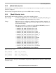
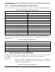
Example 3-7. [Model Selector] uhvio in IBIS File
[Model Selector] uhvio
uhvio_iods0hvf UHVIO, 3.3V, Low Drive
uhvio_iods0lvf UHVIO, 1.875V, Low Drive
uhvio_iods1hvf UHVIO, 3.3V, Medium Drive
uhvio_iods1lvf UHVIO, 1.875V, Medium Drive
Refer to the register description in the IOMUXC chapter in the i.MX53 reference manual for further details
about this model.