
User`s guide


Understanding the IBIS Model
i.MX53 System Development User’s Guide, Rev. 1
3-6 Freescale Semiconductor
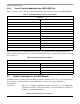
• [Ramp] effectively averages the transitions of the device, without providing any details on the
shapes of the transitions themselves. All detail of the transition ledges would be lost.
The VT data should be included under two [Rising Waveform] and two [Falling Waveform] sections, each
containing data tables for a Vcc-connected load and a Ground-connected load (although other loading
combinations are permitted).
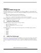
The most appropriate load is a resistive value corresponding to the impedance of the system transmission
lines the buffer will drive (own impedance). For example, a buffer intended for use in a 60 Ω system is
best modeled using a 60 Ω load (R_fixture).
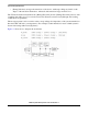
Figure 3-2 shows how to interpret the model data.
Figure 3-2. Model Data Interpretation