
User`s guide


i.MX53 System Development User’s Guide, Rev. 1
Freescale Semiconductor 3-1
Chapter 3
Understanding the IBIS Model
This chapter explains how to use the IBIS (input output buffer information specification) model, which is
an Electronic Industries Alliance standard for the electronic behavioral specifications of integrated circuit
input/output analog characteristics. The model is generated in ACII text format and consists of multiple
tables that capture current vs. voltage (IV) and voltage vs. time (VT) characteristics of the buffer. IBIS
models are generally used to perform PCB-board-level signal integrity (SI) simulations and timing
analyses.
The IBIS model’s features are as follows:
• Supports fast chip-package-board simulation, with SPICE-level accuracy and faster than any
transistor-level model
• Provides the following for portable model data
— I/O buffers, series elements, terminators
— Package RLC parasitics
— Electrical board description
3.1 IBIS Structure and Content
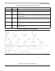
An IBIS file contains the data required to model a component’s input, output, and I/O buffers behaviorally
in ASCII format. The basic IBIS file contains the following data:
• Header information regarding the file itself being modeled
• Information about the component, the package’s electrical characteristics, and the pin-to-buffer
model mapping (i.e., which pins are connected to which buffer models)
• The data required to model each unique input, output, and I/O buffer design on the component
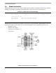
IBIS models are component-centric, meaning they allow users to model an entire component rather than
only a particular buffer. Therefore, in addition to the electrical characteristics of a component’s buffers, an
IBIS file includes the component’s pin-to-buffer mapping and the electrical parameters of the component’s
package.