
User`s guide

i.MX53 Layout Recommendations
i.MX53 System Development User’s Guide, Rev. 1
Freescale Semiconductor 2-5
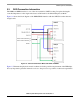
2.3 DDR Connection Information
The DDR2 and DDR3 interface is one of the most critical for i.MX53 routing. It requires having the
controlled impedance for the single ended traces at 50 Ω and for the differential pairs at 100 Ω.
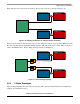
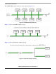
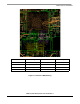
Figure 2-6 shows the block diagram of the DDR2/DDR3 interface with the i.MX53 from the reference
design boards.
Figure 2-6. Connection Between i.MX53 and DDR2 and DDR3
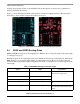
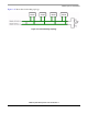
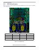
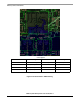
Figure 2-7 illustrates the physical connection scheme for both top and bottom placement of the DDR chips.
It is very important to place the memories as close to the processor as possible to reduce trace capacitance