
User`s guide

i.MX53 System Development User’s Guide, Rev. 1
Freescale Semiconductor 2-1
Chapter 2
i.MX53 Layout Recommendations
This chapter provides recommendations to assist design engineers with the correct layout of their
i.MX53x-based system. The majority of the chapter discusses the implementation of the DDR interface,
but it also provides recommendation for power, the TV encoder, SATA, LVDS, reference resistors, and
ESD and related emissions.
This chapter uses the i.MX53 Quick Start board as its reference when illustrating the key concepts. Refer
to the existing i.MX53 Quick Start board layout files as a companion to this chapter.
2.1 Basic Design Recommendations
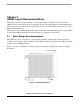
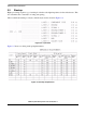
The i.MX53 processor comes in a 19 × 19 mm package with 0.8 mm ball pitch. The ball-grid array
contains 23 rows and 23 columns, making it a 529 ball BGA package. For detailed information about the
package, see the i.MX53 data sheet.
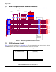
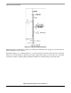
Figure 2-1 provides an illustration of the ball-grid array and Figure 2-2 illustrates additional package
information.
Figure 2-1. i.MX53 Ball-Grid Array