
User`s guide

Design Checklist
i.MX53 System Development User’s Guide, Rev. 1
1-10 Freescale Semiconductor
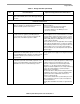
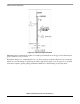
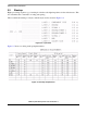
1.4 JTAG Signal Termination
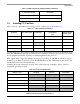
Table 1-5 is a JTAG termination chart (see recommendation 9 and recommendation 10).
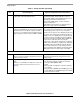
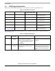
Table 1-6 shows additional JTAG signals that are not required for the processor’s JTAG operation (see
recommendation 33).
Table 1-5. JTAG Interface Summary
JTAG Signal i.MX53 I/O Type
On-Chip Termination
to NVCC_JTAG or GND
External Termination
JTAG_TCK Input 100 kΩ pull-down Not required
Can use 10 kΩ pull down
JTAG_TMS Input 47 kΩ pull-up Not required
Can use 10 kΩ pull up
JTAG_TDI Input 47 kΩ pull-up Not required;
Can use 10 kΩ pull up
JTAG_TDO 3-state output Keeper Do not use pull up or pull down
JTAG_TRSTB Input 47 kΩ pull up Not required
Can use 10 kΩ pull up
JTAG_MOD Input 100 kΩ pull up Required
Use 0 to 6.8 kΩ pull down
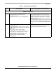
Table 1-6. Additional JTAG Signals
JTAG Signal
System/Target
Pin Type
Requirements or Recommendations Discussion
JTAG_RST_B Driven from ARM
emulator
When utilized:
• Ensure the proper voltage levels.
• Ensure connection point is an open-drain
or wired-OR (diode-OR) to alleviate
contention.
• Install pull-up.
This signal allows the emulator to perform
“Target Reset” from the emulator keyboard
commands.
JTAG_DE_B I/O from ARM
emulator
Employ a 10 kΩ pull-up for general emulator
usage because this signal is tagged as
active-low logic.
This signal functions as a “Debug Request”
and “Debug Acknowledge” between the
emulator and target. Consult the emulator
documentation for proper target design
usage.