
User`s guide

Design Checklist
i.MX53 System Development User’s Guide, Rev. 1
Freescale Semiconductor 1-9
1.3 Avoiding I
2
C Conflicts
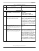
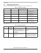
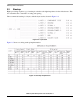
Table 1-3 shows a spreadsheet for avoiding avoid I
2
C conflicts (see recommendation 7).
Note that there are no slave address conflicts. However, the shaded cell does call out a potential bus speed
issue. The AM-FM tuner limits the maximum bus rate to 250 kbps, and the bus data rate cannot exceed the
slowest peripheral on the bus, regardless of which peripheral is being accessed.
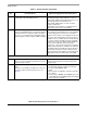
If the system cannot tolerate the 250 kbps rate for proper operation, the AM-FM tuner must be moved to
another I
2
C port. If the I
2
C bus rate exceeds the AM-FM tuner module’s maximum bus rate, the I
2
C bus
operation may fail or become unpredictable.
Assuming the system can function properly with a reduced bus rate of 250 kbps, Table 1-4 shows a
possible I
2
C port usage scenario.
41 kΩ 0.5%
4 1.5 kΩ 0.1%
Table 1-3. I
2
C Bus Example Spreadsheet
Peripheral Bus Activity Level Speed (kbps)
Slave Addresses Supported on
the Peripheral
(hex)
Selected System
Address (hex)
PMIC Low 400 68 68
Port Expander Low 400 30, 32, 34 30
AM-FM Tuner Med
250 C0, C2, C4, C6 C0
A/D Converter Med 400 40, 42 40
Audio CODEC Low 400 90, 92, 94, 96 90
Table 1-4. I
2
C Port Usage Scenario
i.MX53 I
2
C Ports Ball Name Function Speed (kbps)
Port 1
Port 1
Port 2 KEY_ROW3 I2C2_SDA 250
Port 2 EIM_EB2 I2C2_SCL 250
Port 3
Port 3
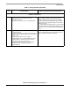
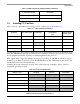
Table 1-2. DDR Vref Resistor Sizing Guideline (continued)
Number of DRAM Packages with
2 μA Vref Input Current
Resistor Divider Value
(2 resistors)