
User`s guide

Design Checklist
i.MX53 System Development User’s Guide, Rev. 1
Freescale Semiconductor 1-7
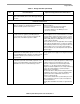
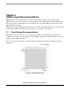
SATA Recommendations
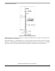
34. The impedance calibration process requires
connecting a 191 Ω 1% reference resistor on
SATA_REXT to ground.
Mount this resistor close to the associated BGA ball.
Module calibration consists of learning which internal
resistor calibration register state causes an internal,
digitally trimmed calibration resistor to best match the
impedance applied to the SATA_REXT. This calibration
register value is then supplied to all internal Tx and Rx
termination resistors.
For < 100 μs during the calibration process, up to 0.3 mW
can be dissipated in the external SATA_REXT resistor. At
other times, no power is dissipated in the SATA_REXT
resistor.
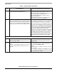
35. For BOOT_MODE1 and BOOT_MODE0, use one of
the following options:
• Achieve logic 0 with any of these three options: tie to
GND through any size external resistor, tie directly to
GND, or float.
• For logic 1, the options are: tie directly to
NVCC_RESET or tie to NVCC_RESET through an
external resistor ≤ 10 kΩ. A value of ≤ 4.7 kΩ is
preferred in high-noise environments.
• If switch control is desired, use 4.7 kΩ to 68 kΩ
pull-down resistors and a SPST switch to
NVCC_RESET.
Boot inputs BOOT_MODE1 and BOOT_MODE0 each
have on-chip pull-down devices with a nominal value of
100 kΩ and a projected minimum of 60 kΩ.
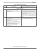
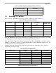
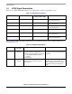
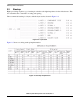
Table 1-1. Design Checklist (continued)
Check
Box
Recommendation Explanation/Supplemental Recommendations