
User`s guide

Design Checklist
i.MX53 System Development User’s Guide, Rev. 1
1-6 Freescale Semiconductor
30. If feeding an external clock into the device, CKIL can
be driven DC-coupled with ECKIL floated.
The logic high level driven into CKIL should be
approximately NVCC_SRTC_POW. Do not exceed
NVCC_SRTC_POW or damage/malfunction may occur.
The CKIL signal should not be driven if the
NVCC_SRTC_POW supply is off. This can lead to
damage or malfunction.
Driving ECKIL is allowed but is not optimum because
ECKIL is the output of the on-chip amplifier.
31. The user should place a 24 MHz fundamental-mode
crystal across XTAL/EXTAL. The crystal must be rated for
a maximum drive level of 100 μW or higher. An ESR of
80 Ω or less is recommended. Freescale BSPs (board
support packages) software requires 24 MHz on EXTAL.
If no TV encoding is required, the tolerance limitation is
due to USB and a crystal with tolerance up to ±225 ppm
(includes aging) may be used. For use of standard
definition TV-out, tolerance up to ±50 ppm may be used.
The crystal can be eliminated if an external oscillator is
available. In this case, EXTAL must be directly driven by
the external oscillator and XTAL is floated. The EXTAL
signal level must swing from NVCC_OSC to GND. If the
clock is used for USB, then there are strict jitter
requirements: < 50 ps peak-to-peak below 1.2 MHz and
< 100 ps peak-to-peak above 1.2 MHz for the USB PHY.
The COSC_EN bit in the CCM (Clock Control Module)
must be cleared to put the on-chip oscillator circuit in
bypass mode which allows EXTAL to be externally driven.
COSC_EN is bit 12 in the CCR register of the CCM.
Reset Recommendations
32. A reset switch may be wired to the i.MX53 POR_B,
which is a cold-reset negative-logic input that resets all
modules and logic in the IC.
The POR_B input must be asserted at power-up and
remain asserted until after the last power rail is at its
working voltage.
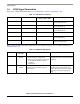
33. Typically, RESET_IN_B is wired to the JTAG reset
signal.
Alternately, connect POR_B to JTAG reset. In this case
assertion of JTAG reset reboots the processor (see
Tabl e 1 - 6 ).
RESET_IN_B is a warm reset negative logic input that
resets all modules and logic except for the following:
• Test logic (JTAG, IOMUXC, DAP)
•SRTC
• Memory repair—Configuration of memory repair per
fuse settings
• Cold reset logic of WDOG—Some WDOG logic is only
reset by POR_B. See the WDOG chapter in the i.MX53
reference manual for details.
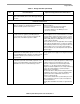
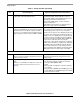
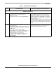
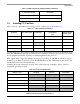
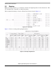
Table 1-1. Design Checklist (continued)
Check
Box
Recommendation Explanation/Supplemental Recommendations