
User`s guide


Design Checklist
i.MX53 System Development User’s Guide, Rev. 1
1-4 Freescale Semiconductor
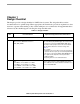
Miscellaneous Signal Recommendations
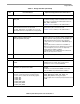
16. Tie FASTR_ANA and FASTR_DIG connections to
GND
FASTR_ANA and FASTR_DIG are reserved for
Freescale manufacturing use only.
17. Float TEST_MODE or tie it to GND. TEST_MODE is for Freescale factory use only. This
signal is internally connected to an on-chip pull-down
device.
18. Float the USB_H1_GPANAIO and
USB_OTG_GPANAIO outputs.
USB_H1_GPANAIO and USB_OTG_GPANAIO are
reserved for Freescale manufacturing use.
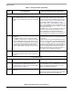
19. Connect SVCC and SVDDGP to test pads to facilitate
measurement of printed circuit board IR drop from
regulator to load.
The SVCC and SVDDGP sense lines provide the ability
to sense voltage levels at the BGA package on their
respective supplies. SVCC is used to monitor VCC and
SVDDGP for VDDGP.
20. For Ethernet access, the MAC address may be stored
in the processor’s fuse bank 1.
—
LVDS Recommendations
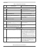
21. For the LVDS_BG_RES input:
• Connect 28 kΩ 1% to GND when the external resistor
option is chosen.
• If LVDS is not used, this signal can be a no connect.
LVDS_BG_RES functions as reference for the LVDS
band-gap circuit. This resistor must be mounted close to
the associated BGA ball.
22. Connect NVCC_LVDS_BG to a 2.5 V supply though
a series 49.9 Ω 1% resistor. Mount this resistor close to
the associated BGA ball. Mount a 0.01 μF decoupling
capacitor near the NVCC_LVDS_BG BGA contact.
NVCC_LVDS_BG functions as a source for the LVDS
band-gap circuit.
USB Recommendations
23. USB_H1_RREFEXT and USB_OTG_RREFEXT
require a separate external 6.04 kΩ 1% resistors to GND.
USB_H1_RREFEXT and USB_OTG_RREFEXT
determine reference currents for USB PHY band gap
references that generate driver current. RREFEXT values
are critical as they affect most of transmitter parameters.
Additional recommendations for resistor connection:
• The connection must be made through a short trace
• The resistance of the connection line should be as low
as possible (< 1 Ω)
• Both of the RREFEXT resistors and connections
should be placed away from noisy regions; Freescale
recommends 2x to 3x adjacent keep out and GND
plane immediately below the trace to reduce coupling.
24. Do not connect the VBUS contacts on the processor
directly to the VBUS contact on the associated USB
connector.
The user must employ a series 47 Ω resistor followed with
a 1 μF capacitor mounted directly at the processor VBUS
BGA ball. In addition, external ESD (electrostatic
discharge) and EOS (electrical overstress) protection is
required at the VBUS BGA ball.
Table 1-1. Design Checklist (continued)
Check
Box
Recommendation Explanation/Supplemental Recommendations