
User`s guide


Design Checklist
i.MX53 System Development User’s Guide, Rev. 1
1-2 Freescale Semiconductor
EIM Recommendations
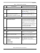
3. When EIM boot signals are used as the system’s EIM
signals or GPIO outputs after boot, use a passive resistor
network to select the desired boot mode for development
boards.
Because only resistors are used, EIM bus loads can
cause current drain, leading to higher (false) supply
current measurements. Each EIM boot signal should
connect to a series resistor to isolate the bus from the
resistors and/or switchers. See Figure 1-1 for the
implementation. Each configured EIM boot signal sees
either a 14.7 kΩ pull-down or a 4.7 kΩ pull-up. For each
switch-enabled pulled-up signal, the supply is presented
with a 10 kΩ current load.
The i.MX53 does not have on-chip keeper circuits on the
external boot inputs, allowing freedom to size boot
resistors larger than some previous i.MX devices.
Production product is booted from the on-chip fuses and
does not employ these external boot mode resistors.
4. To reduce incorrect boot-up mode selections, do one of
the following:
• Use EIM boot interface lines as processor outputs.
• If an EIM boot signal must be configured as an input,
isolate the EIM signal from the target driving source
with one analog switch and apply the logic value with a
second analog switch. Alternately, peripheral devices
with three-state outputs may be used. Ensure the
output is high-impedance during the boot up interval.
Using EIM boot interface lines as inputs may result in a
wrong boot up due to the source overcoming the pull
resistor value.
A peripheral device may require the EIM signal to have an
external or on-chip resistor to minimize signal floating. If
the usage of the EIM boot signal affects the peripheral
device, then an analog switch, open collector buffer, or
equivalent should isolate the path. A pull-up or pull-down
resistor at the peripheral device may be required to
maintain the desired logic level. Review the switch or
device data sheet for operating specifications.
5. Ensure EIM boot interface lines used as outputs are
not loaded down such that the level is interpreted as low
during power up, when the intent is to be a high level, or
vice versa.
—
I
2
C Recommendations
6. Verify the target I
2
C interface clock rates. Remember the bus can only operate as fast as the
slowest peripheral on the bus.
7. Verify the target I
2
C address range is supported and
not conflicting with other peripherals. If there is an
unavoidable address conflict, move the offending device
to another I
2
C port. See Ta bl e 1 - 3.
The i.MX53 supports up to three I
2
C ports.
If it is undesirable to move a conflicting device to another
I
2
C port, review the peripheral operation to see if it
supports re-mapping the addresses.
8. Do not place more than one set of pull-up resistors on
the I
2
C lines.
This can result in excessive loading. Good design
practice is to place a pair of pull-ups only on the
schematic page that has the i.MX53 symbol. Do not place
pull-ups on the pages with the I
2
C peripherals.
Table 1-1. Design Checklist (continued)
Check
Box
Recommendation Explanation/Supplemental Recommendations