
User`s guide


i.MX53 System Development User’s Guide, Rev. 1
Freescale Semiconductor 22-1
Chapter 22
Porting the Fast Ethernet Controller Driver
This chapter explains how to port the fast Ethernet controller (FEC) driver to the i.MX53 processor. Using
Freescale’s standard (FEC) driver makes porting to the i.MX53 simple. Porting needs to address the
following three areas:
• Pin configuration
• Source code
• Ethernet connection configuration
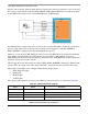
22.1 Pin Configuration
The FEC supports three different standard physical media interfaces: a reduced media independent
interface (RMII), a media independent interface (MII), and a 7-wire serial interface.
The Freescale hardware reference platform directly supports RMII, which has a reduced pin-count
compared to MII. Therefore, RMII is the recommended interface.
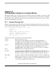
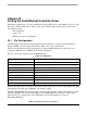
Table 22-1 shows the signals used by the RMII interface.
Because the i.MX53 has more functionality than it has physical I/O pins, it uses I/O pin multiplexing. The
general-purpose I/O pins (gpio1 GPIO[22–31]) default to ALT1.
The FEC_PHY_RESET_B signal comes up by default as gpio2 (pin #0), which is ALT function 1. This
particular signal/pin is used as a simple GPIO to reset the FEC PHY. To use the pins as FEC signals
mentioned above, configure them as the ALT0 function in the I/O multiplexer, except for
FEC_PHY_RESET_B.
Table 22-1. RMII Signals
Signal Name Definition
FEC_TX_CLK (In, Synchronous clock reference)
FEC_TX_EN (Out, Transmit Enable)
FEC_TXD[0:1] (Out, Transmit Data)
FEC_RX_DV (In, Carrier Sense/Receive Data Valid)
FEC_RXD[0:1] (In, Receive Data)
FEC_RX_ER (In, Receive Error)
FEC_MDC (Out, Management Data Clock)
FEC_MDIO (In/Out, Management Data Input/Output)
FEC_PHY_RESET_B (In, PHY reset)