
User`s guide


Supporting the i.MX53 Camera Sensor Interface CSI0
i.MX53 System Development User’s Guide, Rev. 1
Freescale Semiconductor 20-9
20.6 Loading and Testing the Camera Module
If your camera driver has been created as a kernel module, as in the example in this chapter, the module
must be loaded prior any camera request attempt. According to the Makefile information, the camera
module is named ipuv3_csi0_chess_camera.ko.
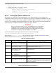
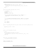
To load the V4L2 camera interface and CSI in test mode, execute the following commands:
root@freescale /unit_tests$ modprobe ipuv3_csi0_chess_camera
root@freescale /unit_tests$ modprobe mxc_v4l2_capture
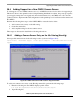
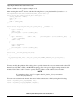
To test the video0 input (camera), an mxc_v4l2_overlay test is included in the BSP. If the imx-test package
has also been included, open the unit test folder and execute the test.
root@freescale ~$ cd /unit_tests/
root@freescale /unit_tests$ ./mxc_v4l2_overlay.out
If the imx-test package has not been built, select it from the LTIB package menu:
Package List > imx-test
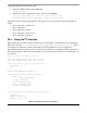
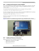
The chessboard appears in a rectangle located on the left top side of the WVGA panel, as shown in
Figure 20-3. The colors of the chessboard toggle between red, green, and blue every time you run the test.
Figure 20-3. Chessboard Test
20.7 Additional Reference Information
This section provides reference information about the following:
• CMOS interfaces supported by the i.MX53
• i.MX53 CSI parallel interface
• Timing data mode protocols