
User`s guide


i.MX53 System Development User’s Guide, Rev. 1
Freescale Semiconductor 20-1
Chapter 20
Supporting the i.MX53 Camera Sensor Interface CSI0
This chapter provides information about how to use the expansion connector to include support for a new
camera sensor on an i.MX53 reference board. It explains how to do the following:
• Configure the CSI unit in test mode (Section 20.3, “Configuring the CSI Unit in Test Mode”)
• Add support for a new CMOS sensor in the i.MX53 BSP (L2.6.31_10.07.11) (Section 20.4,
“Adding Support for a New CMOS Camera Sensor”)
• Set up and use the I
2
C interface to handle your camera bus (Section 20.5, “Using the I
2
C Interface)
• Load and test the camera module (Section 20.6, “Loading and Testing the Camera Module”)
It also provides reference information about the following:
• Required software and hardware
• i.MX53 reference CSI interfaces layout (Section 20.2, “i.MX53 CSI Interfaces Layout”)
• CMOS sensor interfaces (CSI) supported by the i.MX53 (IPU) (Section 20.7.1, “CMOS Interfaces
Supported by the i.MX53)
• i.MX53 EVK CSI parallel interface (Section 20.7.2, “i.MX53 CSI Parallel Interface”)
• i.MX53 CSI test mode (Section 20.7.3, “Timing Data Mode Protocols”)
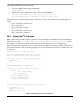
20.1 Required Software
In Freescale BSPs, all capture devices are based on the V4L2 standard. Therefore, only the
CMOS-dependent layer needs to be modified to include a new CMOS sensor; all other layers have been
developed to work with V4L2.
Required development tools are as follows:
• Linux host with i.MX53 Linux L2.6.31_10.07.11 or newer
• Serial port terminal (such as Hyperterminal, TeraTerm, Minicom).