
User`s guide


Connecting an LVDS Panel to an i.MX53 Reference Board
i.MX53 System Development User’s Guide, Rev. 1
19-2 Freescale Semiconductor
The LVDS channel mapping mode and the LDB bit mapping mode of LDB are set according to the boot
up LDB option chosen by the user. If the user has not specified an option but the video mode can be found
in the local video mode database, the driver chooses an appropriate LDB setting. If no video mode is
matched, nothing is done in probe function. Users can set up the LDB later by using ioctrls. The LDB will
be fully enabled in probe function if the driver finds that the primary display device is a single display
device with an LVDS interface.
The steps the driver takes to enable a LVDS channel are as follows:
1. Set ldb_di_clk’s parent clock and the parent clock’s rate.
2. Set ldb_di_clk’s rate.
3. Enable both ldb_di_clk and its parent clock.
4. Set the LDB in a proper mode, including display signals’ polarities, LVDS channel mapping mode,
bit mapping mode, reference resistor mode.
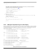
19.2.1 Locating Menu Configuration Options
Linux kernel configuration options are provided for the build-in status to enable this module. To locate
these options, use the following procedure.
1. Go to <ltib dir>.
2. Use the ./ltib -c command.
3. Select Configure the Kernel on the screen displayed and exit.
4. When the next screen appears, follow this sequence: Device Drivers > Graphics support > MXC
Framebuffer support > Synchronous Panel Framebuffer > MXC LDB
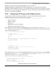
19.2.2 Programming Interface
The APIs in the mxc_ldb_ioctl() function control every other LDB unit setting. The user may call these
these APIs to set LDB modes or to enable and disable the LDB.