
User`s guide


i.MX53 System Development User’s Guide, Rev. 1
Freescale Semiconductor 19-1
Chapter 19
Connecting an LVDS Panel to an i.MX53 Reference Board
This chapter explains how to connect the LVDS panel to an i.MX53 reference board. The i.MX53
processor has an LVDS display bridge (LDB) block that drives LVDS panels without external bridges. The
LDB supports the flow of synchronous RGB data from the IPU to external display devices through the
LVDS interface. This support covers the following activities:
• Connectivity to relevant devices—display with an LVDS receiver.
• Arranging the data as required by the external display receiver and by LVDS display standards.
• Synchronization and control capabilities.
19.1 Connecting an LVDS Panel to the i.MX53 EVK Board
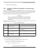
The following LVDS panels were tested on the i.MX53 reference boards:
• LG display (model number: LB150X02)
• 150XG01
• 1080p LVDS panel (model number: M216H1-L01)
• Sharp (model number: LQ084S3LG01)
The kernel command line for 24-bit LVDS panels (4 pairs of LVDSdata signals) displays the following
lines if the panel is properly connected.
DI0 (LDB0 CON2 on top of board): video=mxcdi0fb:RGB24,XGA ldb
DI1 (LDB1 CON3 on bottom of board): video=mxcdi1fb:RGB24,XGA di1_primary ldb
The kernel command line for 18-bit LVDS panels (3 pairs of LVDS data signals) displays the following
lines if the panel is properly connected.
DI0 (LDB0 CON2 on top of board): video=mxcdi0fb:RGB666,XGA ldb
DI1 (LDB1 CON3 on bottom of board): video=mxcdi1fb:RGB666,XGA di1_primary ldb
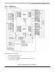
19.2 Enabling an LVDS Channel
The LDB driver source code is available at <ltib_dir>/rpm/BUILD/linux/drivers/video/mxc/ldb.c. To
make a built-in LDB driver functional, add the ‘ldb’ option to the kernel command line. The driver
configures the LDB when the device is probed.
When the LDB device is probed properly, the driver uses platform data information to configure the LDB’s
reference resistor mode and regulator. The LDB driver probe function also tries to match video modes for
external display devices with an LVDS interface. The display signal polarities and LDB control bits are
set according to the matched video modes.