
User`s guide

Configuring the SPI NOR Flash Memory Technology Device (MTD) Driver
i.MX53 System Development User’s Guide, Rev. 1
16-4 Freescale Semiconductor
16.4.3 Changing the Chip Select
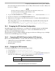
To change the chip select used, locate the file at arch/arm/mach-mx5/mx53_<board name>.c and use the
static struct spi_board_info mxc_dataflash_device[] __initdata structure.
Replace the value of ".chip_select" variable with the desired chip select value. For example,
.chip_select = 3 sets the chip select to number 3 on the CSPI interface.
16.4.4 Changing the External Signals
The iomux-mx53.h file contains the definitions for all i.MX53 pads. Add entries in this file to define the
configuration for the CSPI function. See Chapter 13, “Configuring the IOMUX Controller (IOMUXC),”
for a description of how to set up the IOMUX and pads for routing signals as desired.
NOTE
Check the mxc_iomux_pins structure to ensure that the chosen signal
chosen is not used by another interface before configuration.
16.5 Hardware Operation
SPI NOR Flash is SPI compatible with frequencies up to 66 MHz. The memory is organized in pages of
512 bytes or 528 bytes. SPI NOR Flash also contains two SRAM buffers of 512/528 bytes each, which
allows data reception while a page in the main memory is being reprogrammed as well as the writing of a
continuous data stream.
Unlike conventional Flash memories that are accessed randomly, the SPI NOR Flash accesses data
sequentially. It operates from a single 2.7–3.6 V power supply for program and read operations.
SPI NOR Flashes are enabled through a chip select pin and accessed through a three-wire interface: serial
input, serial output, and serial clock.
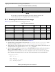
ECSPI-2 &mxcspi2_device
CSPI &mxcspi3_device
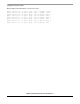
Table 16-3. CSPI Parameters (continued)
CSPI Parameter Name