
User`s guide


Configuring the IOMUX Controller (IOMUXC)
i.MX53 System Development User’s Guide, Rev. 1
13-6 Freescale Semiconductor
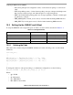
Define the pad on iomux-mx53.h file as follows:
#define MX53_PAD_ATA_DA_1__GPIO_7_7IOMUX_PAD(0x614, 0x294, 1, 0x0, 0, NO_PAD_CTRL)
Parameters:
• 0x614—PAD Control Offset
• 0x294—MUX Control Offset
• 1—MUX Mode
• 0x000—Select Input Offset
• 0—Select Input
• NO_PAD_CTRL—Pad Control
To register the pad, add the previously defined pin to the pad description structure in the mx53_<reference
board name>.c file, as shown in the following code.
static struct pad_desc mx53common_pads[] = {
…
…
…
MX53_PAD_ATA_DA_1__GPIO_7_7,
…
…
…
};
To use the pad as GPIO, go to the i.MX53 Linux command line. On this line, it is possible to test the GPIO
exporting its number on /sys/class/gpio/export.
This number is formed by <GPIO Instance – 1> × 32 + <GPIO Port number>. In this example GPIO7_7
is being used, so its number is (7 – 1) × 32 + 7 = 199.
Export the GPIO7_7:
echo 199 > /sys/class/gpio/export
Set GPIO199 as output:
echo out > /sys/class/gpio/gpio199/direction
Set output as 1 or 0:
echo 1 > /sys/class/gpio/gpio199/value
echo 0 > /sys/class/gpio/gpio199/value
If the steps above were performed correctly, the pin PATA_DA_1 toggles on the i.MX53 reference board
when the board is running the system.