
User`s guide


Configuring the IOMUX Controller (IOMUXC)
i.MX53 System Development User’s Guide, Rev. 1
Freescale Semiconductor 13-5
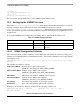
The variables are as follows:
• 0x620—PAD Control Offset
• 0x2A0—MUX Control Offset
• 4—MUX Mode
• 0x888—Select Input Offset
• 3—Select Input
• MX53_UART_PAD_CTRL—Pad Control
For all addresses and register values, check the IOMUX chapter in the i.MX53 Applications Processor
Reference Manual.
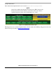
13.3.2 Machine Layer File
The mx53_<reference board name>.c file contains structures for configuring the pads. They are declared
as follows:
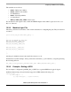
static struct pad_desc mx53common_pads[] = {
…
…
…
MX53_PAD_ATA_BUFFER_EN__UART2_RXD,
MX53_PAD_ATA_DMARQ__UART2_TXD,
MX53_PAD_ATA_DIOR__UART2_RTS,
MX53_PAD_ATA_INTRQ__UART2_CTS,
MX53_PAD_ATA_CS_0__UART3_TXD,
MX53_PAD_ATA_CS_1__UART3_RXD,
…
…
…
};
Add the pad's definitions from iomux-mx53.h to the above code.
On init function (in this example “mx53_<reference board name>_io_init” function), set up the pads using
the following function:
mxc_iomux_v3_setup_multiple_pads(mx53common_pads, ARRAY_SIZE(mx53common_pads));
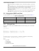
13.3.3 Example—Setting a GPIO
For an example, configure the pin PATA_DA_1 (PIN L3) as a general GPIO and toggle its signal.
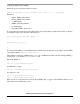
On Kernel menuconfig, add sysfs interface support for GPIO with the following code:
Device Drivers --->
[*] GPIO Support --->
[*] /sys/class/gpio/... (sysfs interface)