
User`s guide


Configuring the IOMUX Controller (IOMUXC)
i.MX53 System Development User’s Guide, Rev. 1
Freescale Semiconductor 13-3
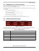
• pi—PAD Control Offset
13.2.2 Configuring IOMUX Pins for Initialization Function
The mx53<reference board name>.c file contains the initialization functions for all peripherals (such as
UART, I
2
C, and Ethernet). Configure the relevant pins for each initializing function, using the following:
mxc_request_iomux(<pin name>, <iomux config>);
mxc_iomux_set_input(<mux input select>, <mux input config>);
mxc_iomux_set_pad(<pin name>, <iomux pad config>);
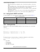
Where the following applies:
<pin name> See all pins definitions on file mx53_pins.h
<iomux config> See parameters defined at iomux_config enumeration on file iomux.h
<iomux input select> See parameters defined at iomux_input_select enumeration on file iomux.h
<iomux input config> See parameters defined at iomux_input_config enumeration on file iomux.h
<iomux pad config> See parameters defined at iomux_pad_config enumeration on file iomux.h
13.2.3 Example—Setting a GPIO
For an example, configure and use pin PATA_DA_1 (PIN L3) as a general GPIO and toggle its signal.
Add the following code to the file mx53_<reference board name>.c, function board_init:
// Request ownership for an IO pin.
mxc_request_iomux(MX53_PIN_ATA_DA_1, IOMUX_CONFIG_ALT1);
// Set pin as 0
reg = readl(GPIO7_BASE_ADDR + 0x0);
reg &= ~0x80;
writel(reg, GPIO7_BASE_ADDR + 0x0);
// Set pin direction as output
reg = readl(GPIO7_BASE_ADDR + 0x4);
reg |= 0x80;
writel(reg, GPIO7_BASE_ADDR + 0x4);
// Delay 0.5 seconds
udelay(500000);
// Set pin as 1
reg = readl(GPIO7_BASE_ADDR + 0x0);
reg |= 0x80;
writel(reg, GPIO7_BASE_ADDR + 0x0);
// Delay 0.5 seconds
udelay(500000);