
User`s guide


i.MX53 System Development User’s Guide, Rev. 1
Freescale Semiconductor 8-1
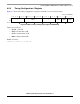
Chapter 8
Using the Clock Connectivity Table
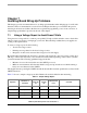
This chapter explains how to use the i.MX53 clocking connectivity. This information can help users save
power by disabling clocks to unused modules.
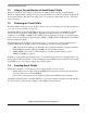
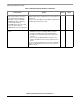
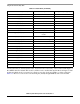
Table 8-1 describes the available clock sources and lists the maximum frequencies that are supported by
design. In some cases if maximum frequency is used, users need to divide the clock inside the module in
order to meet the protocol requirements. The clock controller module (CCM) generates and drives the
clock sources.
For information about how the root clocks are generated, see the clock generation diagrams in the CCM
chapter of the i.MX53 reference manual. In some cases, the CCM does not generate the clock, and the
clock may come directly from the IO pad.
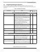
Table 8-1. Clock Roots
Clock Root Name (from CCM) Description Target Frequency [MHz]
arm_clk_root Root of ARM high frequency 1000
arm_axi_clk_root Root for ARM AXI clock 200
emi_slow_clk_root Root for EMI slow arbitrator 133
debug_apb_clk_root Root for debug busses of ARM 200
ddr_clk_root Root of DDR clock 400
enfc_clk_root Root for NFC controller 66.5
vpu_axi_clk_root Root for VPU AXI clock 200
vpu_rclk_root Root for reference clock for VPU 66.5
spdif0_clk_root Root of SPDIF-0 clock 66.5
spdif1_clk_root Root of SPDIF-1 clock 66.5
ahb_clk_root Root of AHB clock 133
ipg_clk_root Root of IPG clock 66.5
asrc_clk_root — 66.5
perclk_root Root of PERCLK 66.5
usboh3_clk_root Root of USB clock 66.5
esdhc1_clk_root Root clock for ESDHC-1 and MSHC-1 104
esdhc2_clk_root Root clock for ESDHC-2 104
esdhc3_clk_root Root for ESDHC-3 clock 104
esdhc4_clk_root Root for ESDHC-4 clock 104