
User`s guide


i.MX53 System Development User’s Guide, Rev. 1
Freescale Semiconductor 7-1
Chapter 7
Avoiding Board Bring-Up Problems
This chapter provides recommendations for avoiding typical mistakes when bringing up a board for the
first time. These recommendations consist of basic techniques that have proven useful in the past for
detecting board issues and address the three most typical bring-up pitfalls: power, clocks, and reset. A
sample bring-up checklist is provided at the end of the chapter.
7.1 Using a Voltage Report to Avoid Power Pitfalls
Using incorrect voltage rails is a common power pitfall. To help avoid this mistake, create a basic table
called a voltage report prior to bringing up your board. This table helps validate that your supplies are
coming to the expected level.
To create a voltage report, list the following:
• Your board voltage sources
• Default power-up values for the board voltage sources
• Best place on the board to measure the voltage level of each supply
Be careful when determining the best place to measure each supply. In some cases, a large voltage drop
(IR drop) on the board may cause you to measure inaccurate levels depending on the location you take
your measurement. The following guidelines help prevent this:
• Measure closest to the load (in this case the i.MX53 processor).
• Make two measurements: the first after initial board power-up and the second while running a
heavy use-case that stresses the i.MX53.
The supplies that are powering the i.MX53 should all meet the DC electrical specifications as listed in the
i.MX53 data sheet.
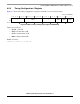
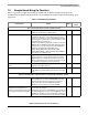
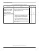
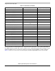
Table 7-1 shows a sample voltage report table. Blank cells would be filled in after measuring.
Table 7-1. Sample Voltage Report
Regulator
Net Name on
Schematic
Default
Power Up
(V)
Measured
Voltag e
(V)
Measurement
Point
Comment
— VBAT 12 J1 pin 1
Wall supply 5V_MAIN 5 J2 pin 4
Switcher 1 1V8_MAIN 1.8 C11 0402, near U3, inch below j37
Switcher 2 3V3_MAIN 3.3 C14 0603, right next to C11