
User`s guide
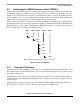


Setting up Power Management
i.MX53 System Development User’s Guide, Rev. 1
5-6 Freescale Semiconductor
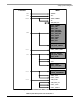
5.2.1 Connecting Power and Communication Signals
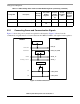
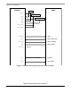
Figure 5-3 shows the power connections required for the interface. Figure 5-4 shows how the
communication signals must be connected between the i.MX53, DA9053, and required extra regulators.
Figure 5-3. Power Connections
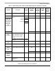
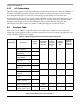
VP S-ATA PHY Core power supply 1.3 LDO5 1.3 100 4
VPH S-ATA PHY I/O supply voltage 2.5 VBUCKPERI_
SW
2.475 1000 4
1
External DCDC part number is RT8010
Table 5-1. i.MX53 Voltage Rails and Associated DA9053 Regulator (continued) (continued)
Voltage Rail Description
Nominal
Voltage
Associated
DA9053
Regulator
Voltag e S et
Point of
DA9053
Regulator
(V)
Current
Capability
(mA)
Power up
Sequence
Set at the
DA9053
POR_B
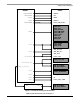
i.MX53 DA9053
NRESET
GPIO_5
NVDD_FAULT
SK
SO
CSIO_DAT9
CSIO_DAT8
NVCC_RESET
NIRQ
GPIO_16
NVCC_CSI
NONKEY
PMIC_ON_REQ
NVCC_GPIO