MVC-PTZ-23X Indoor/Outdoor 23× PTZ Speed Dome Camera Quick Installation Guide 5101 NW 21st Ave, Suite 210 • Fort Lauderdale, FL 33309 www.mace.
Table of Contents 1 QUICK INSTALLATION SPEED DOME INSTALLATION ................................... 7 1.1 Installation Preparation ......................................................................................................................... 7 1.2 Installation............................................................................................................................................... 8 1.2.1 Address and Baud Rate Setup .......................................................
4 HANG MOUNT BRACKET INSTALLATION ..................................................... 18 4.1 Component Installation ....................................................................................................................... 18 4.2 Installation............................................................................................................................................. 18 4.2.1 Installation Requirements .......................................................................
Welcome Thank you for purchasing our speed dome! Please read the following safeguards and warnings carefully before you install or use the product! 4
Important Safeguards and Warnings Safety Measures Qualified Engineer Needed z The installation engineer or maintenance engineer shall have corresponding CCTV system installation certificate or maintenance qualification certificate. z The installation engineer or maintenance engineer shall have qualification certificate for work at height.
z We are not liable for any problems caused by unauthorized modifications or attempted repair. Do not allow other object falling into the device z z z Please make sure there is no metal or inflammable, explosive substance in the speed dome. The above mentioned objects in the device may result in fire, short-circuit or damage. Please shut down the device and disconnect the power cable if there is water or liquid falling into the camera. Please contact your local retailer ASAP.
1 QUICK INSTALLATION SPEED DOME INSTALLATION 1.1 Installation Preparation Basic Requirement z z All installation and operation here should conform to your local electrical safety codes. Before installation, please open the package and check all the components are included. Please make sure the speed dome installation environment and installation mode can meet your requirement. If there is special requirement, please contact your local retailer for more information.
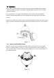
1.2 Installation Please note the quick installation speed dome includes the quick installation high speed dome, IP quick installation speed dome, tracing quick installation high speed dome, quick installation medium speed dome. The speed dome has several types of installation brackets. You can refer to the following contents for detailed information. Here we are going to install the speed dome in wall mount bracket.
1.2.2 Install the transparent cover First, you need to check the steel wire of the bracket is firmly secure or not. Please line up the captive screws to the quadrate groove of the bracket and then push the bracket into the internal enclosure. Fix these two captive screws. See Figure 1-3. Figure 1-3 Now you can install the quick installation port. Please twist Teflon tape around the screw thread of the quick installation port and turn it into the screw thread of the wall mount bracket.
Figure 1-5 Note The video port is covered the heat shrink tube of high shrinking ratio. After the video connection, please heat the tube to make sure the video port is damp proof and water proof. 1.2.3 Install the speed dome After you complete the above steps, please pull the integration cable and multiple-function composite cable to the wall mount bracket.
Figure 1-6 Important After the installation, please make sure: z The three stainless screws of the quick installation port are firmly secure. z The quick installation speed dome is fixed. z The speed dome is straight. z The steel wire connection is firm. After your installation, the interface is shown as in Figure 1-7. Figure 1-7 1.
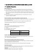
The default setup is: z Address: 1 z Baud rate: 9600 1.4 Dial Switch Setup The two dial switches of the speed dome are SW1 and SW2. These are to specify the speed dome parameter such as protocol, baud rate, address and etc. When the button is ON, it is 1. In the SW1 and SW2, 1 is the lowest bit and the 8 is the highest bit. See Figure 1-8. Please note this series speed dome cans automatically recognize the DH-SD, PELCO-D. PELCO-P. Usually you do not need to set the protocol. Figure 1-8 1.4.
ON ON 1200bps Please refer to the parity setup sheet for detailed information. 7 8 Parity OFF OFF NONE ON OFF EVEN OFF ON ODD ON ON NONE 1.4.2 Address Setup The speed dome address setup interface is shown as below. See Figure 1-9. Figure 1-9 The encode mode adopts binary system. 1 to 8 is valid bit. The highest address bit is 255. You can refer to the following sheet for more information.
2 BRACKET DIMENSIONS 2.1 Wall mount bracket The wall mount bracket dimensions are shown as below. See Figure 2-1. Figure 2-1 2.2 Hanging mount bracket (Multiple Lengths) The hanging mount bracket is shown as below. See Figure 2-2. The bracket length setup values are: z 200mm z 300mm z 500mm You just need to replace the connection pole.
2.3 Corner mount bracket The corner mount bracket is shown as below. See Figure 2-3. Figure 2-3 2.4 Pole mount bracket The corner mount bracket is shown as below. See Figure 2-4.
3 WALL MOUNT BRACKET INSTALLATION 3.1 Component Installation Wall mount bracket is shown as below. See Figure 3-1. Figure 3-1 3.2 Installation 3.2.1 Installation Requirements The wall mount speed dome can be installed in the hard construction wall in the indoor or outdoor environments. Before the installation, please make sure: z The wall is thick enough to install the expansion bolt. z The wall can at least sustain the 4x weight of the speed dome. 3.2.
Install the speed dome in the bracket. See Figure 3-3. Figure 3-3 Please refer to chapter 1.2 for detailed installation information.
4 HANG MOUNT BRACKET INSTALLATION 4.1 Component Installation Hang mount bracket and its components are shown as below. See Figure 4-1. Figure 4-1 4.2 Installation 4.2.1 Installation Requirements The hang mount speed dome can be installed in the hard construction wall in the indoor or outdoor environments. Before the installation, please make sure: z The wall is thick enough to install the expansion bolt. z The wall can at least sustain the 4x weight of the speed dome. 4.2.
Pull the cable through the steeve and then secure the steeve to the flange. Fix the M4 bolt. Please note, if the speed dome is installed in the outdoor environments, you need to paste enough Teflon tape at the top screw thread of the steeve and then turn the steeve to the flange firmly. Please paste the silica gel on the steeve connection surface to do the waterproof work. See Figure 4-4.
5 CORNER MOUNT BRACKET INSTALLATION 5.1 Component Installation Corner mount bracket and its components are shown as below. See Figure 5-1. Figure 5-1 5.2 Installation 5.2.1 Installation Requirements The corner mount speed dome can be installed in the hard construction wall in the indoor or outdoor environments where there is a 90 degrees angle. Before the installation, please make sure: z The wall is thick enough to install the expansion bolt.
Figure 5-3 Please refer to chapter 1.2 for detailed installation information.
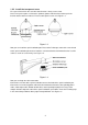
6 POLE MOUNT BRACKET INSTALLATION Pole mount bracket and its components are shown as below. See Figure 6-1. Figure 6-1 6.1 Installation 6.1.1 Installation Requirements The corner mount speed dome can be installed in the hard construction wall in the indoor or outdoor environments. Before the installation, please make sure the pole bracket can sustain the 4X weight of the speed dome. The diameter of the pole structure shall comply with the installation dimension of the clamp.
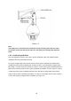
Clamp and pole bracket connection Pole bracket and the pole connection Figure 6-3 After you installed bracket and external cover, loosen the captive screws and open the panel, pull the power cable through the hanging bracket and then fix the hanging bracket to the wall. Please pay attention to the waterproof between the bracket and the wall. See Figure 6-4. Figure 6-4 Please refer to chapter 1.2 for detailed installation information.
7 APPENDIX Ⅰ THUNDER PROOF AND SURGE PROTECTION This series speed dome adopts TVS lighting protection technology. It can effectively prevent damages from various pulse signals below 1500W, such as sudden lighting and surge. While maintaining your local electrical safety code, you still need to take necessary precaution measures when installing the speed dome in the outdoor environment.
8 APPENDIX Ⅱ ABOUT RS485 BUS 8.1 RS485 Bus Main Feature RS485 is semi duplex communication cable of impedance 120Ω. Its max load amount is 32 effective loads (including main control device and devices to be charged). 8.2 RS485 Bus Transmission Distance When we take 0.56mm (24AWG) twisted-pair as communication cable, the max transmission distance (theoretically) are listed below (according to different baud rates).
Figure 8-2 8.4 RS485 Bus FAQ Phenomenon Speed dome can run selfdiagnosis but I can not control it.