
User Manual


Table Of Contents
- 169000_RevF - Final - A Series OM Cover MACDON for WEB.pdf
- 169000_RevF - A Series OM FINAL w DofC for WEB
- back page
- new cover_WEB.pdf
- toc
- Model and Serial Number
- 1Safety
- 2Definitions
- 3Component Identification
- 4Specifications
- 5Operation
- 5.1Owner/Operator Responsibilities
- 5.2Operational Safety
- 5.3Tractor Setup: Pull-Type
- 5.4Mower Conditioner / Tractor Hook-Up: Pull-Type
- 5.5Mower Conditioner / Tractor Unhook: Pull-Type
- 5.6Header Attachment: Self-Propelled
- 5.7Configure Reverser Valve Jumper Hose
- 5.8Header Detachment: Self Propelled
- 5.9Transporting Header/Mower Conditioner
- 5.10Break-In Period
- 5.11Preseason Check
- 5.12Daily Start-Up Check
- 5.13Shutdown Procedure
- 5.14Engaging the Power Take-Off (PTO): Pull-Type
- 5.15Lift Cylinder Lockouts
- 5.16Steering the Pull-Type Mower Conditioner
- 5.17Unplugging the Header/Mower Conditioner
- 5.17.1Unplugging Conditioner and Knife: Pull-Type
- 5.17.2Unplugging Conditioner: Self-Propelled
- 5.17.3Unplugging Conditioner and Knife: Self-Propelled
- 5.18Header Operation
- 5.18.1Lean Bar Position
- 5.18.2Auger Speed
- 5.18.3Reel Speed
- 5.18.4Auger Position
- 5.18.5Reel Position
- 5.18.6Adjusting Tine Aggressiveness
- 5.18.7Cutting Height
- 5.18.8Header Angle
- 5.18.9Flotation
- 5.18.10Adjusting Feed Pan and Rock Drop Tine Position
- 5.18.11Hay Conditioner
- 5.18.12Adjusting Roll Tension
- 5.18.13Forming Shields
- 5.18.14Tall Crop Dividers
- 5.18.15Ground Speed
- 5.18.16Grass Seed Windrowing
- 5.18.17Haying Tips
- 5.18.18Storage
- 6Maintenance and Servicing
- 6.1Preparation for Servicing
- 6.2Recommended Safety Procedures
- 6.3Maintenance Specifications
- 6.4Driveshields
- 6.5Lift Cylinder Lock-Outs
- 6.6Lubrication
- 6.7Hydraulics
- 6.8Knife and Knife Drive
- 6.8.1Replacing Knife Section
- 6.8.2Sickle Removal
- 6.8.3Installing Knife
- 6.8.4Sickle Head Bearing Removal
- 6.8.5Sickle Head Bearing Installation
- 6.8.6Spare Sickle
- 6.8.7Sickle Guards
- 6.8.8Sickle Hold-Downs
- 6.8.9Sickle Drive Belt: A30-S
- 6.8.10Sickle Drive Belts: A30-D
- 6.8.11Sickle Drive Belts: A40-D
- Adjusting Tension on Knife Drive Timing Belt – A40-D Left Side
- Adjusting Tension on Knife Drive Timing Belt – A40-D Left Side
- Removal: A40-D LH Sickle Drive Timing Belt
- Removal: A40-D LH Sickle Drive Timing Belt
- Installing Knife Drive Timing Belts – A40-D Left Side
- Installing Knife Drive Double V-Belts – A40-D Left Side
- Adjusting Tension on Knife Drive Belt – A40-D Right Side
- Removing Knife Drive Belt – A40-D Right Side
- Installing Knife Drive Belt – A40-D Right Side
- 6.8.12Sickle Drive Belt Timing Adjustment
- 6.8.13Knife Drive Box
- 6.9Reel Drive Belts: A30-S, A30-D
- 6.10Reel Tines and Tine Bar Bearings – A30-D
- 6.11Reel and Reel Drive: A30-S, A30-D
- 6.12Reel and Reel Drive: A40-D
- 6.13Auger and Auger Drive – A30-D
- 6.14Auger and Auger Drive – A40-D
- 6.15Conditioner
- 6.15.1Changing Gearbox Oil
- 6.15.2Removing Forming Shield
- 6.15.3Disassembling Forming Shield
- 6.15.4Assembling Forming Shield
- 5.Attach adjuster rods (B) to side deflectors (C) with lynch pin (A).
- 6.15.5Installing Forming Shield
- 6.15.6Hydraulic Drive Motor Removal: All Models
- 6.15.7Hydraulic Drive Motor Installation: All Models
- 6.15.8Gearbox Removal: A30-S
- 6.15.9Gearbox Installation: A30-S
- 6.15.10Gearbox Removal: A30-D
- 6.15.11Gearbox Installation: A30-D
- 6.15.12Gearbox Removal: A40-D
- 6.15.13Gearbox Installation: A40-D
- 6.16Wheels and Tires – A30-D
- 6.17Replacing Skid Shoe Wear Plate
- 6.18Gauge Rollers
- 6.19Maintaining Electrical System
- 6.20Maintenance Schedule
- 7Troubleshooting
- 8Options and Attachments
- 9Unloading and Assembly
- Model and Serial Number
- toc
SECTION 7 MAINTENANCE AND SERVICING
169000 150 Revision F
7.11.5.2 Replacing Stripper Bar
WARNING
To avoid bodily injury or death from
unexpected start-up or fall of raised
machine, stop engine, remove key, and
engage lift cylinder stops before going
under machine.
a. Remove four nuts and bolts (A) that secure each
stripper bar (B) (LH and RH) to the pan, and
remove bars. There are six bars in total.
b. Position new bars (B) on pan as shown, with
upper flange on front bar facing forward.
c. Install three bolts and nuts (A) in each bar, and
torque to 150 ft·lbf (203 N·m).
d. Check clearance between auger and
stripper bars.
e. Loosen bolts (A), and add shims between
stripper bars and pan at bolt locations as
required to obtain clearance as shown.
f. Retighten bolts to specified torque.
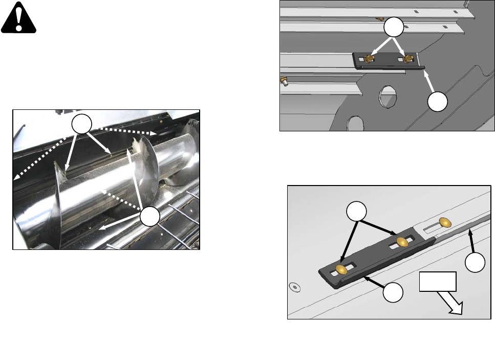
7.11.5.3 Front Stripper Bar Extensions
Extensions for the front stripper bar are provided
for installation (if required for certain crop
conditions), or especially in tall crops that cause
material to bunch up at the ends of the
conditioner rolls.
Stripper bar extensions will allow the auger to
carry the crop more towards the center, rather
than prematurely feeding it to the conditioner.
a. Raise header, and engage lift cylinder stops.
b. Remove nuts and carriage bolts (C) securing the
two extensions (D) to underside of header pan
support, and retain for reinstallation.
c. Position extension (D) at inboard end of front
stripper bars (E), and mark locations of the two
holes onto the plastic pan.
d. Drill two 5/16 in. (8 mm) holes at these locations.
e. Install extension with carriage bolts (C) removed
at sub-step b.
f. Repeat above steps for other extension.
7.12 AUGER AND AUGER DRIVE:
A40-D
The A40-D header auger is driven directly from
a hydraulic motor, and there are no belts or
chains to maintain.
For auger and stripper bar maintenance
procedures, refer to Section 7.11.3 Auger Pans,
Section 7.11.4 Rubber Fingers, and Section
7.11.5 Stripper Bars.
D
C
LH SIDE
(AUGER NOT SHOWN FOR CLARITY)
D
E
C
FWD
B
A