
User guide
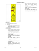

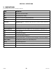
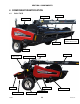
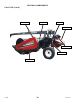
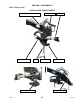
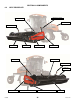
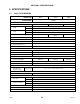

Table Of Contents
- 169000_RevF - Final - A Series OM Cover MACDON for WEB.pdf
- 169000_RevF - A Series OM FINAL w DofC for WEB
- back page
- new cover_WEB.pdf
- toc
- Model and Serial Number
- 1Safety
- 2Definitions
- 3Component Identification
- 4Specifications
- 5Operation
- 5.1Owner/Operator Responsibilities
- 5.2Operational Safety
- 5.3Tractor Setup: Pull-Type
- 5.4Mower Conditioner / Tractor Hook-Up: Pull-Type
- 5.5Mower Conditioner / Tractor Unhook: Pull-Type
- 5.6Header Attachment: Self-Propelled
- 5.7Configure Reverser Valve Jumper Hose
- 5.8Header Detachment: Self Propelled
- 5.9Transporting Header/Mower Conditioner
- 5.10Break-In Period
- 5.11Preseason Check
- 5.12Daily Start-Up Check
- 5.13Shutdown Procedure
- 5.14Engaging the Power Take-Off (PTO): Pull-Type
- 5.15Lift Cylinder Lockouts
- 5.16Steering the Pull-Type Mower Conditioner
- 5.17Unplugging the Header/Mower Conditioner
- 5.17.1Unplugging Conditioner and Knife: Pull-Type
- 5.17.2Unplugging Conditioner: Self-Propelled
- 5.17.3Unplugging Conditioner and Knife: Self-Propelled
- 5.18Header Operation
- 5.18.1Lean Bar Position
- 5.18.2Auger Speed
- 5.18.3Reel Speed
- 5.18.4Auger Position
- 5.18.5Reel Position
- 5.18.6Adjusting Tine Aggressiveness
- 5.18.7Cutting Height
- 5.18.8Header Angle
- 5.18.9Flotation
- 5.18.10Adjusting Feed Pan and Rock Drop Tine Position
- 5.18.11Hay Conditioner
- 5.18.12Adjusting Roll Tension
- 5.18.13Forming Shields
- 5.18.14Tall Crop Dividers
- 5.18.15Ground Speed
- 5.18.16Grass Seed Windrowing
- 5.18.17Haying Tips
- 5.18.18Storage
- 6Maintenance and Servicing
- 6.1Preparation for Servicing
- 6.2Recommended Safety Procedures
- 6.3Maintenance Specifications
- 6.4Driveshields
- 6.5Lift Cylinder Lock-Outs
- 6.6Lubrication
- 6.7Hydraulics
- 6.8Knife and Knife Drive
- 6.8.1Replacing Knife Section
- 6.8.2Sickle Removal
- 6.8.3Installing Knife
- 6.8.4Sickle Head Bearing Removal
- 6.8.5Sickle Head Bearing Installation
- 6.8.6Spare Sickle
- 6.8.7Sickle Guards
- 6.8.8Sickle Hold-Downs
- 6.8.9Sickle Drive Belt: A30-S
- 6.8.10Sickle Drive Belts: A30-D
- 6.8.11Sickle Drive Belts: A40-D
- Adjusting Tension on Knife Drive Timing Belt – A40-D Left Side
- Adjusting Tension on Knife Drive Timing Belt – A40-D Left Side
- Removal: A40-D LH Sickle Drive Timing Belt
- Removal: A40-D LH Sickle Drive Timing Belt
- Installing Knife Drive Timing Belts – A40-D Left Side
- Installing Knife Drive Double V-Belts – A40-D Left Side
- Adjusting Tension on Knife Drive Belt – A40-D Right Side
- Removing Knife Drive Belt – A40-D Right Side
- Installing Knife Drive Belt – A40-D Right Side
- 6.8.12Sickle Drive Belt Timing Adjustment
- 6.8.13Knife Drive Box
- 6.9Reel Drive Belts: A30-S, A30-D
- 6.10Reel Tines and Tine Bar Bearings – A30-D
- 6.11Reel and Reel Drive: A30-S, A30-D
- 6.12Reel and Reel Drive: A40-D
- 6.13Auger and Auger Drive – A30-D
- 6.14Auger and Auger Drive – A40-D
- 6.15Conditioner
- 6.15.1Changing Gearbox Oil
- 6.15.2Removing Forming Shield
- 6.15.3Disassembling Forming Shield
- 6.15.4Assembling Forming Shield
- 5.Attach adjuster rods (B) to side deflectors (C) with lynch pin (A).
- 6.15.5Installing Forming Shield
- 6.15.6Hydraulic Drive Motor Removal: All Models
- 6.15.7Hydraulic Drive Motor Installation: All Models
- 6.15.8Gearbox Removal: A30-S
- 6.15.9Gearbox Installation: A30-S
- 6.15.10Gearbox Removal: A30-D
- 6.15.11Gearbox Installation: A30-D
- 6.15.12Gearbox Removal: A40-D
- 6.15.13Gearbox Installation: A40-D
- 6.16Wheels and Tires – A30-D
- 6.17Replacing Skid Shoe Wear Plate
- 6.18Gauge Rollers
- 6.19Maintaining Electrical System
- 6.20Maintenance Schedule
- 7Troubleshooting
- 8Options and Attachments
- 9Unloading and Assembly
- Model and Serial Number
- toc

SECTION 5 SPECIFICATIONS
169000 28 Revision F
PULL-TYPE HEADERS (cont’d)
NOTES: 1. Specifications and design are subject to change without notice or obligation to revise previously sold units.
HEADER SIZE 14 FT 16 FT 18 FT
HEADER MODEL A30-D
AUGER
Drive Mechanical 2 Belts To Chain
Size
Tube 10 in. (254 mm) O.D
Flighting 20 in. (508 mm) O.D., 0.25 in. (6 mm) thick.
Type
Undershot, Center Feed. Rubber Finger Feed.
Stripper Bars
3 Per Side
Speed
(rpm)
20T Sprocket
No Load 275
Load 265
19T Sprocket
No Load 261
Load 252
Delivery Opening
95.7 in. (2430 mm)
REEL
Drive Mechanical 2 Belts From Auger To Chain Final Drive
Type
Bats 5-Bat (6-Bat Optional)
Tines Steel: 0.25 in. (6 mm) Diameter
Tine Bar Bearings
Replaceable Polyethylene
Radius (to tine tip)
22 in. (540 mm)
Speed
(rpm)
20T
Sprocket
20T
Auger
No Load 74
Load 71
19T
Auger
No Load 70
Load 68
19T
Sprocket
20T
Auger
No Load 70
Load 68
19T
Auger
No Load 67
Load 64
CONDITIONER
Drive Hydraulic M44 (44cc) Motor To Enclosed Gearbox
Roll Type
Intermeshing Steel Bars
Roll Diameter
Bars 9.17 in. (233 mm) O.D.
Tube 6.63 in. (168 mm) O.D.
Roll Length
102 in. (2590 mm)
Roll Speed (rpm)
No Load - 766 Load - 736
Swath Width
36 in. (915 mm) to 100 in. (2540 mm)
Unplugging Assist
Rolls Open As Header Lifts. Rolls Can Open to 4.25 in. (108 mm) During Operation
Forming Shields
Header Mounted Adjustable Baffle and Side Deflector System
For 36 in. (915 mm) to 100 in. (2540 mm) Swath Width
OPERATING SPEED
Recommended Cutting 5 mph (8 km/hr)
Recommended Transport 20 mph (30 km/hr)
TRACTOR REQUIREMENTS
Power (minimum) 90 HP (68 kW) 110 HP (83 kW) 130HP (98 kW)
Hydraulics 2000 psi (13,714 kPa)