
User guide
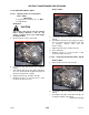

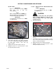
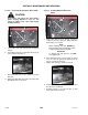


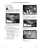
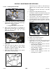


Table Of Contents
- 169000_RevF - Final - A Series OM Cover MACDON for WEB.pdf
- 169000_RevF - A Series OM FINAL w DofC for WEB
- back page
- new cover_WEB.pdf
- toc
- Model and Serial Number
- 1Safety
- 2Definitions
- 3Component Identification
- 4Specifications
- 5Operation
- 5.1Owner/Operator Responsibilities
- 5.2Operational Safety
- 5.3Tractor Setup: Pull-Type
- 5.4Mower Conditioner / Tractor Hook-Up: Pull-Type
- 5.5Mower Conditioner / Tractor Unhook: Pull-Type
- 5.6Header Attachment: Self-Propelled
- 5.7Configure Reverser Valve Jumper Hose
- 5.8Header Detachment: Self Propelled
- 5.9Transporting Header/Mower Conditioner
- 5.10Break-In Period
- 5.11Preseason Check
- 5.12Daily Start-Up Check
- 5.13Shutdown Procedure
- 5.14Engaging the Power Take-Off (PTO): Pull-Type
- 5.15Lift Cylinder Lockouts
- 5.16Steering the Pull-Type Mower Conditioner
- 5.17Unplugging the Header/Mower Conditioner
- 5.17.1Unplugging Conditioner and Knife: Pull-Type
- 5.17.2Unplugging Conditioner: Self-Propelled
- 5.17.3Unplugging Conditioner and Knife: Self-Propelled
- 5.18Header Operation
- 5.18.1Lean Bar Position
- 5.18.2Auger Speed
- 5.18.3Reel Speed
- 5.18.4Auger Position
- 5.18.5Reel Position
- 5.18.6Adjusting Tine Aggressiveness
- 5.18.7Cutting Height
- 5.18.8Header Angle
- 5.18.9Flotation
- 5.18.10Adjusting Feed Pan and Rock Drop Tine Position
- 5.18.11Hay Conditioner
- 5.18.12Adjusting Roll Tension
- 5.18.13Forming Shields
- 5.18.14Tall Crop Dividers
- 5.18.15Ground Speed
- 5.18.16Grass Seed Windrowing
- 5.18.17Haying Tips
- 5.18.18Storage
- 6Maintenance and Servicing
- 6.1Preparation for Servicing
- 6.2Recommended Safety Procedures
- 6.3Maintenance Specifications
- 6.4Driveshields
- 6.5Lift Cylinder Lock-Outs
- 6.6Lubrication
- 6.7Hydraulics
- 6.8Knife and Knife Drive
- 6.8.1Replacing Knife Section
- 6.8.2Sickle Removal
- 6.8.3Installing Knife
- 6.8.4Sickle Head Bearing Removal
- 6.8.5Sickle Head Bearing Installation
- 6.8.6Spare Sickle
- 6.8.7Sickle Guards
- 6.8.8Sickle Hold-Downs
- 6.8.9Sickle Drive Belt: A30-S
- 6.8.10Sickle Drive Belts: A30-D
- 6.8.11Sickle Drive Belts: A40-D
- Adjusting Tension on Knife Drive Timing Belt – A40-D Left Side
- Adjusting Tension on Knife Drive Timing Belt – A40-D Left Side
- Removal: A40-D LH Sickle Drive Timing Belt
- Removal: A40-D LH Sickle Drive Timing Belt
- Installing Knife Drive Timing Belts – A40-D Left Side
- Installing Knife Drive Double V-Belts – A40-D Left Side
- Adjusting Tension on Knife Drive Belt – A40-D Right Side
- Removing Knife Drive Belt – A40-D Right Side
- Installing Knife Drive Belt – A40-D Right Side
- 6.8.12Sickle Drive Belt Timing Adjustment
- 6.8.13Knife Drive Box
- 6.9Reel Drive Belts: A30-S, A30-D
- 6.10Reel Tines and Tine Bar Bearings – A30-D
- 6.11Reel and Reel Drive: A30-S, A30-D
- 6.12Reel and Reel Drive: A40-D
- 6.13Auger and Auger Drive – A30-D
- 6.14Auger and Auger Drive – A40-D
- 6.15Conditioner
- 6.15.1Changing Gearbox Oil
- 6.15.2Removing Forming Shield
- 6.15.3Disassembling Forming Shield
- 6.15.4Assembling Forming Shield
- 5.Attach adjuster rods (B) to side deflectors (C) with lynch pin (A).
- 6.15.5Installing Forming Shield
- 6.15.6Hydraulic Drive Motor Removal: All Models
- 6.15.7Hydraulic Drive Motor Installation: All Models
- 6.15.8Gearbox Removal: A30-S
- 6.15.9Gearbox Installation: A30-S
- 6.15.10Gearbox Removal: A30-D
- 6.15.11Gearbox Installation: A30-D
- 6.15.12Gearbox Removal: A40-D
- 6.15.13Gearbox Installation: A40-D
- 6.16Wheels and Tires – A30-D
- 6.17Replacing Skid Shoe Wear Plate
- 6.18Gauge Rollers
- 6.19Maintaining Electrical System
- 6.20Maintenance Schedule
- 7Troubleshooting
- 8Options and Attachments
- 9Unloading and Assembly
- Model and Serial Number
- toc
SECTION 7 MAINTENANCE AND SERVICING
169000 133 Revision F
7.8.11 Adjusting Knife Drive Timing
Double knife A30-D and A40-D Auger Headers
require that the knives are properly timed to
move in opposite directions.
CAUTION
Stop engine, and remove key from ignition
before leaving Operator’s seat for any
reason. A child or even a pet could engage
an idling machine.
a. Remove the right side knife drive belt. Refer to
Section 7.8.9.5 Removing RH Knife Drive
Timing Belt – A30-D, or Section 7.8.10.5
Removing RH Knife Drive Belt – A40-D.
b. Rotate LH side knife drive box driven pulley (A)
CLOCKWISE until LH side knife (B) is at the
center of the inboard stoke (moving towards
center of header).
NOTE
Center stroke is when the knife sections
are centered between guard points
as shown.
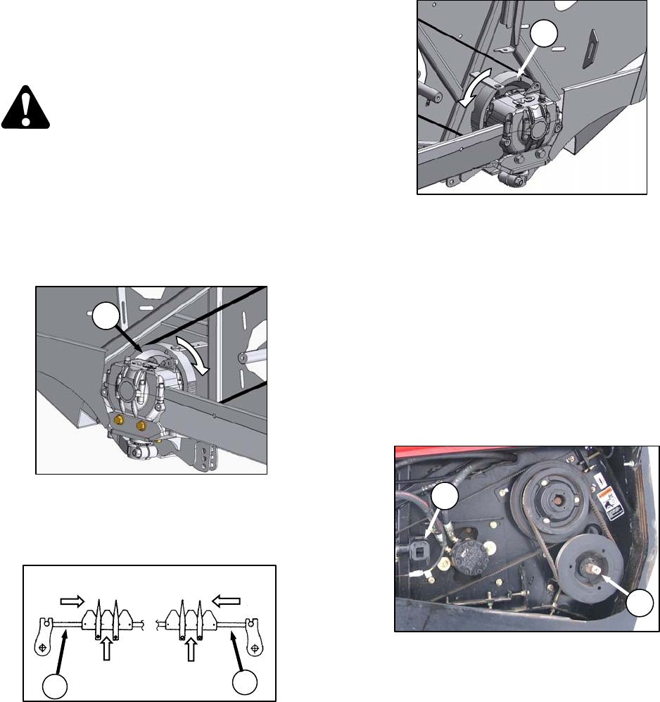
c. Rotate right side knife drive box pulley (C)
COUNTERCLOCKWISE until right side
knife (D) is at the center of the inboard stroke.
d. Install right side knife drive box drive belt and
tension. Refer to Section 7.8.9.6 Installing RH
Knife Drive Belt – A30-D, or 7.8.10.6 Installing
RH Knife Drive Belt – A40-D.
IMPORTANT
To maintain timing, knife drive box driver
and driven pulleys must NOT rotate as the
belt is tightened.
e. Check that timing belts are properly seated in
the grooves on both driver and driven pulleys.
f. Check for correct knife timing by rotating
driveshaft (E) slowly with the unplug wrench (F),
and observe knives where they overlap at the
center of the header.
IMPORTANT
Knives must move in opposite directions,
and must begin moving at exactly the
same time.
(continued next page)
F
E
RIGHT
KNIFE
LEFT
KNIFE
DIRECTION OF
MOVEMENT
SECTIONS CENTERED
BETWEEN GUARDS
B
D
A
C