
Operating instructions


TM 5-4310-452-14
4-13. VALVE CLEARANCE ADJUSTMENT (Con't).
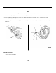
3. Loosen locknut (3) on rocker arm (5), Insert 0.15
mm (0.006 in.) feeler gage between rocker arm and
top of valve stem (6). Turn setscrew (4) until a
slight drag can be felt on feeler gage.
4. Tighten locknut (3) and check valve clearance.
Repeat step 3 if necessary.
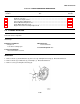
5. Turn crankshaft pulley (1) counterclockwise
(direction of rotation) one complete revolution
(360° from position 1).
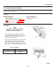
6. Check valve clearance between rocker arm (5) and
top of valve stem (6) of valves (2) in position 2
using Table 4-5 and a 0.15 mm (0.006 in.) feeler
gage. If valve clearance is too wide or too narrow,
repeat steps 3 and 4. If valve clearance is OK, go
to step 7.
Table 4-5. Position 2.
Cylinder NO. Valve
1 Intake Exhaust
2 Exhaust
3 Intake
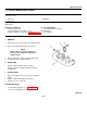
7. Check clearance of all valves and adjust if
necessary
FOLLOW-ON TASKS:
• Install valve covers (see paragraph 4-12).
• Connect battery cables (see paragraph 4-57).
• Close left and right door assemblies.
4-23