
Operating instructions


TM 5-4310-452-14
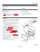
4-55. INDICATOR PANEL ASSEMBLY REPLACEMENT (Con't).
INSTALLATION
1. Position gage panel (9) in frame (8) and install 4
screws (10) and nuts (7).
2. Position indicator panel assembly (13) in place in
housing.
3. Install engine oil pressure gage (see paragraph 4-
54).
4. Install oil pressure switch (see paragraph 4-41).
5. Install ammeter (see paragraph 4-53).
6. Install tach/hourmeter (see paragraph 4-52).
7. Install discharge pressure gage and fuel pressure
gage (see paragraph 4-51).
8. Install compressor oil temperature gage and fuel
level gage (see paragraph 4-50).
9. Position window (11) in place on housing over
indicator panel assembly (13) and install 8 screws
(12).
10. Position lamp assembly (3) in place on compressor
unit and install starwasher (4) and nut (5).
Connect 2 wire leads (6) to lamp assembly.
11. Install bulb (2) and hood (1) on lamp assembly (3).
FOLLOW-ON TASKS:
• Connect battery cables -(see paragraph 4-57).
• Close left door assembly.
4-102